27
Single-phase outdoor unit
The size of outdoor unit stop valve(mm)
Gas Side
Liquid Side
18
Φ15.9
Φ9.52
Outdoor unit
model (
kW
)
NOTE
Check if any accessory in the above figure is
missing. All the accessories must be kept
properly.
All the fittings should be factory fittings.
Wired/Remote controller — purchase
separately.
Outlet sealant — purchase separately.
All the figures in the manual explain only the
general appearance and dimensions of the
unit. The air conditioner you purchased may
not be completely consistent with the
appearance and functions listed in the figures.
Please refer to the actual product.
3. OUTDOOR UNIT
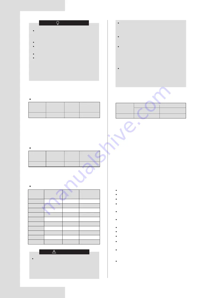
3.1 Outdoor Unit Combination Ratio
ODU model
(
kW
)
Capacity of
ODU
(horsepower)
Number of
IDUs
Combination
Ratio
Capacity
(kW)
Capacity
(horsepower)
Capacity
(kW)
Capacity
(horsepower)
Table 3-3
Table 3-1
Capacity conversion table
18
1.5
1.8
2.2
2.5
2.8
3.2
3.6
4.0
4.5
5.0
0.6
0.7
0.8
0.9
1.0
1.1
1.2
1.5
1.7
1.8
2.0
2.2
2.5
3.0
3.2
3.6
4.0
4.5
5.0
6.0
5.6
6.3
7.1
8.0
9.0
10.0
11.2
12.5
14.0
16.0
6.5
1~12
50%~160%
Three-phase outdoor unit
ODU model
(
kW
)
Capacity of
ODU
(horsepower)
Number of
IDUs
Combination
Ratio
Table 3-2
18
6.5
1~12
50%~160%
CAUTION
The total capacity of the IDUs, measured in
horsepower, must not exceed 160% of the
capacity of the ODU. When the combination
ratio of IDUs exceeds 100%, the output capacity
of the system may decrease.
When the startup capacity of the IDUs is greater
than 130% of the ODU, the operating fan speed
of IDUs is limited to low speed.
The heating capacity of the system decreases
as the ambient outdoor temperature decreases.
In areas where the design heating temperature
of the air conditioner is ≤5°C and the unit needs
to be fully switched on, the combination ratio of
indoor units is recommended not to exceed
110%.
In areas where the design heating temperature
of the air conditioner is ≤0°C and the unit needs
to be fully switched on, the combination ratio of
indoor units is recommended not to exceed
100%.
4. PREPARATIONS BEFORE
INSTALLATION
4.1 Choosing and Preparing the
Installation Site
3.2 Outdoor unit Stop Valve Size
4.1.1 Site requirements
Table 3-4
A place where there is combustible gas leakage.
A place where there is a lot of oil (including engine oil).
A place where there is salty air (locations near the coast)
A place where there is caustic gas (sulfide, for
example) present in the air (near a hot spring)
A place where the heated air expelled out from the
outdoor unit can reach your neighbor’s window.
A place where the noise interferes with your
neighbors’ everyday life.
A place that is too weak to bear the weight of the unit
An uneven place.
A place with insufficient ventilation.
Near a private power station or high frequency
equipment.
Install the indoor unit, outdoor unit, power cord and
connecting wire at least 1 m away from a TV set or
radio to prevent noise or picture interference.
Install the unit in a place that can offer enough space
for installation and maintenance. Don’t install it in a
place that has high requirements regarding noise,
such as in a bedroom.
Please refrain from installing the unit in the following
places, or malfunction of the machine may occur:


