OPERATION
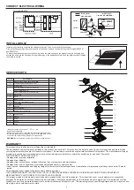
PLAN THE INSTALLATION
TYPES OF TYPICAL INSTALLATIONS
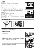
1. Do not use in a cooking area.
2. Two ways to connect ductwork to a factory-shipped unit.
ASSEMBLY INSTRUCTIONS
1. Housing mounted to I-joists (Start at “ASSEMBLY INSTRUCTIONS 1”)
2. Housing mounted to joists (Start at “ASSEMBLY INSTRUCTIONS 1” )
3. Housing mounted to truss (Start at step “ASSEMBLY INSTRUCTIONS 2”)
2
-
+
-
+
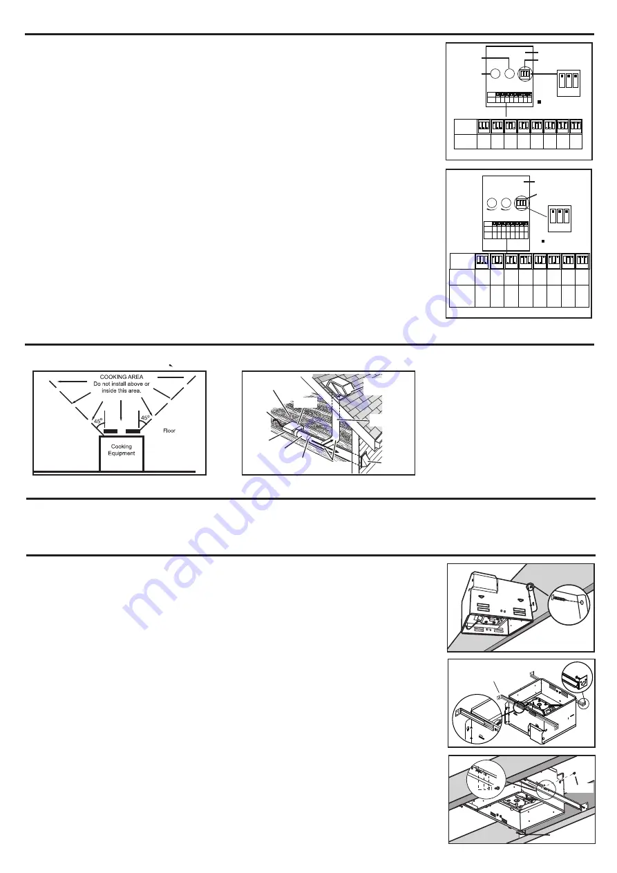
1 2 3
1 2 3
Toggle switch
Power box
80 90 110 120 90 110 120 140
1 2 3
1 2 3
1 2 3
1 2 3
1 2 3
1 2 3
1 2 3
1 2 3
6"
Switch
position
Duct
diameter
(inches)
Air deliver
(CFM)
6"
6"
6"
4"
4"
4"
4"
80 90 110 120 90 110 120 140
1 2 3
1 2 3
1 2 3
1 2 3
1 2 3
1 2 3
1 2 3
1 2 3
6"
Switch
position
Duct
diameter
(inches)
Air deliver
(CFM)
6"
6"
6"
4"
4"
4"
4"
is the position
of switch
DC MOTOR FOR SED110
ROOF CAP*
(with built-in
damper)
ROUND
DUCT*
WALL CAP*
(with built-in
damper)
*
Purchase
separately
POWER
CABLE*
INSULATION*
(Place around and
over Fan Housing.)
Seal gaps
around
Housing.
FAN
HOUSING
ROUND
ELBOW(S) *
Seal duct
joints with
tape.
Keep duct
runs short
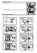
Hold the housing so that it is in contact with the bottom of the joist. Attach the housing with four (4) screws to the joist through
the holes in each mounting flange.
1. MOUNT HOUSING TO JOIST OR I-JOIST.
HANGER
BAR
2. MOUNT WITH HANGER BARS
2a. Sliding hanger bars have been provided, which allow the housing to be positioned accurately anywhere between the
framing. The bars span up to 24 in. and can be used on all types of framing: I-joist, standard joist, and truss construction.
Slide hanger bars onto housing and adjust as needed to fit between framing.
NAIL
2b. Extend the hanger bars to the width of the framing. Position the ventilator with the hanger bar tabs wrapped around the
bottom edge of the framing, holding the ventilator in place.
Secure hanger bars to framing using one screw on each end of hanger bar.
Select a proper hole and secure the hanger bars together using flange screws.
SCREW
FOR SE90TMH
Fan run continuously at a low speed (setted by toggle switch,factory-set is “OFF”) and
automatically boost up to the certified airflow rate when either of these conditions is
detected:
(a) whenever someone enter or leave the room.
(b) humidity above a user-adjustable setpoint (50%-100% relative humidity).
After delay timer returns fan to the default low speed or stop.
1 2 3
1 2 3
Toggle switch
Power box
Time knob
Humidity
sensor knob
OFF
50%
30% 40%
70% 80%
60%
90%
1 2 3
1 2 3
1 2 3
1 2 3
1 2 3 1 2 3
1 2 3
1 2 3
Switch
position
Air deliver
(CFM)
OFF
50%
30% 40%
70% 80%
60%
90%
1 2 3
1 2 3
1 2 3
1 2 3
1 2 3 1 2 3
1 2 3
1 2 3
Switch
position
Air deliver
(CFM)
is the position
of switch
T
H
For SE90TMH
For SED110
The control box, located inside the fan housing, has three separate adjustments:
(1) The low airflow knob adjusts the lower airflow from 30CFM up to the air flow rate of the high fan speed
determined by the toggle switch setting.
(2) The time delay knob is adjustable from 3 to 30 minutes and will switch the fan to the low speed setting
after motion is no longer detected in the room for the set period of time.
(3) The toggle switch will adjust the upper fan speed setting from 80 to 120 CFM ,using a 4" duct, or 90 to
140 CFM using a 6" duct. Both 4" & 6" duct adaptors are included.
How to work
To Turn Fan ON
Turn the switch I (according to the following “CONNECT ELECTRICAL WIRING” ) ON.
• Fan will run at the certified airflow rate if the switch II is ON.
• Fan will run at the user-adjustable airflow rate if the switch II is OFF.
To Use Fan Time Delay Airflow Rate Change
1. Turn the switch I ON.
2. Turn the switch II ON - fan will run at the certified airflow rate.
3. When the switch II is turned OFF, fan will continue to run at the certified airflow rate until the
user-adjustable time delay has elapsed, and then will automatically change to the user-adjustable airflow rate.
To Turn Fan OFF
Turn the switch I OFF


