


ASSEMBLY INSTRUCTIONS
Run 120 V AC house wiring to the location of the fan. Use only UL-approved connectors (not included) to attach the house wiring to the
wiring plate. Refer to the wiring diagram, and connect the wires as shown.
CONNECT ELECTRICAL WIRING
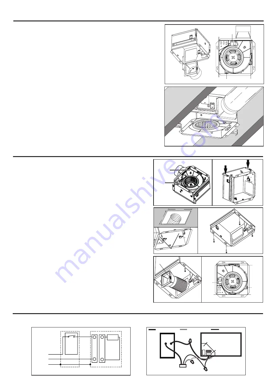
5. INSTALL ROUND DUCTWORK
a. Connect the round ductwork (not included) to the damper/duct connector, and run the
ductwork to a roof or wall cap (not included).
b. Using tape (not included), secure all the ductwork connections so that they are air tight.
c. Insulated flexible duct is recommended for the quietest possible installation. If rigid
duct is used, a short (1-3 feet) section of insulated flexible duct will ensure quiet
operation.
The ducting from this fan to the outside of building has a strong effect on the air flow,
noise and energy use of the fan. Use the shortest, straightest duct routing possible for
best performance, and avoid installing the fan with smaller ducts than recommended.
Insulation around the ducts can reduce energy loss and inhibit mold growth. Fans
installed with existing ducts may not achieve their rated air flow.
4. Install DUCT AND BLOWER ASSEMBLY
Hole
Hole
Hole
a.Install duct from the inside of the housing;Fix the duct by the tab.
b.Fix the BLOWER ASSEMBLY to the housing by 3 screws.
RETROFIT INSTALLATION
1. Remove wire panel and blower assembly before installation.
2. Fold mounting ears flat against housing.
Blower
assembly
Wire
panel
3. Enlarge ceiling opening to 9-1/2” by 9-1/2”, leave ductwork and wiring in place.
4. Connect wiring according to the wiring diagram.Re-install wire panel.
5. Mounting fan
a. Mount with additional mounting holes
The interior of the fan housing contains additional mounting holes in case
exterior mounting is not possible.
Screw or nail the fan housing directly to the framing or joists.
Remove the blower assembly as directed in the service parts section of this
manual to gain access to the additional mounting holes.
b. Mount with hole of the flange
Use screws (included) to screw fans to the ceiling through the holes of the
housing.
6. Connect duct
Pull existing ducting through housing discharge opening and tape ducting to
duct connector. Push connector/ducting back through opening,fix the duct by
the tab.
7. Install the blower assembly.
additional mounting holes
Hole
Hole
Hole
Tab
9-1/2”
9-1/2”
UNIT
BLACK (BLK)
SWITCH BOX
FAN
POWER SUPPLY
120V AC
GROUND (GRD)
WHITE (WHT)
WIRING
PLATE
FAN
RECEPTACLE
FAN
UNIT
SWITCH BOX
LINE
IN
ON/OFF
SWITCH
BLK
BLK
WHT
WHT
GRD
GRD
SNP100
3


