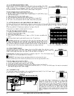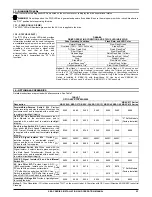
KBAC SERIES INSTALLATION AND OPERATION MANUAL
11
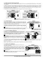
FIGURE 7
KBAC-217, 217S, 217F, 217SF, 416, 416S, 416F, 416SF DRIVE LAYOUT (SEE LEGEND BELOW FOR NUMBERED ITEMS)
L1
L2
L3
AC LINE
U
W
MOTOR
V
LEGEND:
1.
Connector CON3: For diagnostic LED board. See Section 13 on page 23.
2.
Terminals RUN, COM, STOP: For factory installed Start/Stop Switch. See Section 7.5 on page 17.
3.
Terminals FWD, STOP, REV: For optional Forward-Stop-Reverse Switch. See Section 14 on page 23.
4.
Terminals P1, P2, P3: For factory installed Main Speed Potentiometer. See Section 7.4 on page 16.
5
. Terminal Block TB2: Run/Fault Relay Output Contacts. See Section 7.9 on page 18.
6
. Jog Terminal: Used with optional Run-Stop-Jog Switch Kit. See Section 14 on page 23.
7
. Adjustable Trimpots: Maximum Speed (MAX), Minimum Speed (MIN), Acceleration (ACCEL), Deceleration (DECEL), DC Injection Brake
(DECEL), Boost (BOOST), Current Limit (CL), Jog (JOG), Slip Compensation (COMP). See Section 12 on pages 21 and 22.
8.
Selectable
Jumpers:
Motor Horsepower (J2), Automatic Ride-Through or Manual Start (J3), Frequency Multiplier (J4), Motor Frequency
(J5), Fixed or Adjustable Boost (J6), Regeneration or DC Injection Braking (J7), "Run" or "Fault" Output Relay Operation (J8), Normally
Open or Closed Stop Contact (J9), Constant or Variable Torque (J10), Switching Frequency and GFCI (J12). See Section 10 on pages 19
and 20.
9.
Connector CON1: Used to connect optional accessories to the drive.
10.
Four mounting holes for optional Signal Isolator. See Section 14 on page 23.
11.
Terminals L1A, L2A, L3A: Used for factory installed On/Off AC Line Switch and factory installed RFI Filter Kit. See Section 14 on page 23.
12.
Terminal Block TB1: AC Line input and Motor connections. See Sections 7.1 and 7.2 on page 15 and 16.
13.
Ground Screws: Chassis (earth ground).


