KBAC SERIES INSTALLATION AND OPERATION MANUAL
18
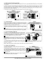
7.9 – RUN/FAULT RELAY CONNECTION
The Run/Fault Relay Output Contacts are located at Terminal Block TB2 and can be used to turn
equipment on or off or to signal a warning if the drive is put into the Stop Mode or a fault has occurred.
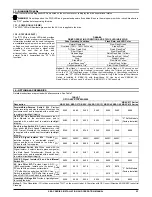
See Figure 20. The Run/Fault Relay Contact status for various drive operating conditions is shown in
Table 5.
8 – RECOMMENDED HIGH VOLTAGE DIELECTRIC WITHSTAND TESTING (HI-POT TESTING)
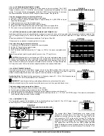
Testing agencies such as UL, CSA, VDE, etc., usually require that equipment undergo a hi-pot test. In order to prevent catastrophic damage
to the drive which has been installed in the equipment, the following procedure is recommended. A typical hi-pot test setup is shown in Figure
21. All drives have been factory hi-pot tested in accordance with UL requirements.
WARNING!
All equipment AC Line inputs must be disconnected from the AC power.
Connect all equipment AC power input lines together and connect them to the H.V. lead of the hi-pot tester. Connect the RETURN lead of the
hi-pot tester to the frame on which the drive and other auxiliary equipment are mounted.
The hi-pot tester must have an automatic ramp-up to the test voltage and an automatic ramp-down to zero voltage.
Note: If the hi-pot tester does not have automatic ramping, then the hi-pot output must be manually increased to the test voltage and then
manually reduced to zero. This procedure must be followed for each machine to be tested. A suggested hi-pot tester is Slaughter Model 2550.
CAUTION!
Instantly applying the hi-pot voltage will cause irreversible damage to the drive, which will void the warranty.
FIGURE 21
TYPICAL HI-POT TEST SETUP
AC Line Input
9 – RECONDITIONIONG THE BUS CAPACITORS
If this drive has been in storage for over one year it is necessary to recondition the power supply bus capacitors. To recondition the bus
capacitors, apply the AC Line, with the drive in the Stop Mode, for a minimum of one hour. Not following this procedure will cause the bus
capacitors to fail.
FIGURE 20
RUN/FAULT RELAY OUTPUT
CONTACTS CONNECTION
WARNING! HIGH VOLTAGE!
See Warning on page 15.
TABLE 5
DRIVE OPERATING CONDITION AND RUN/FAULT RELAY CONTACT STATUS
Drive
Operating
Condition Description
Run Relay Operation
(J8 set to the "R" Position)
(Factory Setting)
Run Relay Operation
(J8 set to the "R" Position)
Normally
Open
Contact
Normally
Closed
Contact
Normally
Open
Contact
Normally
Closed
Contact
Power Off
Main Power Disconnected Open
Closed
Open
Closed
Run Mode
1
Normal
Drive
Operation Closed Open
Closed
Open
Stop Mode
1
Selected by Operator Open Closed
Closed
Open
Fault
2
Drive
Tripped Open
Closed
Open
Closed
Notes: 1.
Run Mode or Stop Mode is selected using the Start/Stop Switch.
2.
Overload, I
2
t, Short
Circuit, Undervoltage and Overvoltage.


