background image


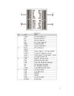
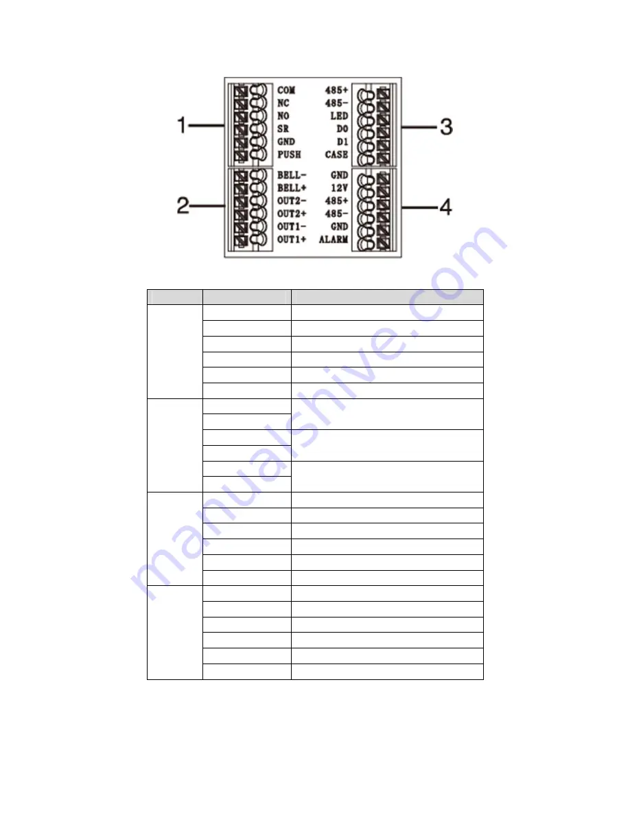
Figure 3- 2 

No. 

Port 

Note 

COM 

Door lock COM end 

NC 

Door lock NC end 

NO 

Door lock NO end 

SR 

Door sensor detection 

GND 

Connect to GND 

PUSH 

Press unlock button 

BELL- 

Door bell output 

BELL+ 

OUT2- 

Alarm  output  2

5V  level  switch

),

connect to voltage not over 12V 

OUT2+ 

OUT1- 

Alarm output 1

5V level switch

, connec 

to voltage not over 12V 

OUT1+ 

485+ 

RS485+, 485 card reader 

485- 

RS485-, 485 card reader 

LED 

LED_OUT, Weigand card reader 

D0 

D0, Weigand card reader 

D1 

D1, Weigand card reader 

CASE 

Card reader protection alarm 

GND 

Connect to GND 

12V 

12V power input 

485+ 

RS485+ 

485- 

RS485- 

GND 

Connect to GND 

ALARM 

Alarm input 


Summary of Contents for KX-DR01

Page 1: ...1 Fingerprint Access Control Integration Host User s Manual V1 0 0 ...

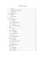
Page 2: ... 4 2 2 Add Super Password 7 4 2 3 Delete User 8 4 2 4 Add More Master Card 9 4 3 A C 9 4 3 1 Period 9 4 3 2 Master Card 12 4 3 3 Unlock Mode 12 4 3 4 Door Lock Time 13 4 3 5 Alarm 13 4 3 6 Door Status Setup 14 4 4 System Settings 15 4 4 1 Local Setup 15 4 4 2 Communication Setup 16 4 4 3 Mode 17 4 4 4 Reboot System 17 4 5 System Info 17 4 5 1 Card History 18 4 5 2 Alarm History 18 4 5 3 Local Info...

Page 3: ...or quilt Do not block air vent of the device or ventilation around the device Otherwise temperature in device will rise and may cause fire Do not place any object on the device Do not disassemble the device without professional instruction Warning Please use battery properly to avoid fire explosion and other dangers Please replace used battery with battery of the same type Do not use power line ot...

Page 4: ...ard fingerprint password card password card fingerprint card or password or fingerprint Max support 4 500 fingerprints 30 000 valid cards and 500 super passwords Max support 150 000 card records and 512 alarm records Door time out alarm intrusion alarm duress alarm and door sensor alarm Ring input Add guest card duress card black white list and patrol card while support period of validity or times...

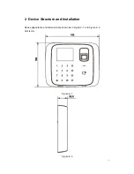
Page 5: ...1 2 Device Structure and Installation Device appearance and dimension are shown as in Figure 2 1 and Figure 2 2 Unit is mm Figure 2 1 Figure 2 2 ...

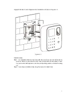
Page 6: ...x installation bracket in the hole on 86 box via screw A as to fix the bracket on wall if no 86 box or you cannot fix it well then use screw B to fix the bracket on wall but you must embed expansion nut at the corresponding position in wall before doing so Step 2 According to installation map hang the device on bracket hook ...

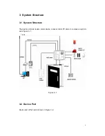
Page 7: ...tem Structure 3 1 System Structure The device and card reader alarm device access control PC and etc compose a system as in Figure 3 1 Figure 3 1 3 2 Device Port Device port of the host is shown in Figure 3 2 ...

Page 8: ...utput 2 5V level switch connect to voltage not over 12V OUT2 OUT1 Alarm output 1 5V level switch connec to voltage not over 12V OUT1 3 485 RS485 485 card reader 485 RS485 485 card reader LED LED_OUT Weigand card reader D0 D0 Weigand card reader D1 D1 Weigand card reader CASE Card reader protection alarm 4 GND Connect to GND 12V 12V power input 485 RS485 485 RS485 GND Connect to GND ALARM Alarm inp...

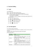
Page 9: ... 2 User Management You can add or delete card password You also can add user as you add card or fingerprint and you can bind card and fingerprint Card type includes general VIP guest patrol black list and duress Please refer to Chart 4 1 Card Type Note General card General user card When you add card system will ask if set card password period and term of validity VIP card VIP user card It warns s...

Page 10: ...s user who input password in setup to enter Note Card user has not set password and you shall set unlock mode to card card or password or fingerprint in order to enter Card user set card password and you shall set unlock mode to card card password card or password or fingerprint in order to enter Card user set fingerprint but before entering user shall set unlock mode to card card password card or...

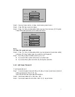
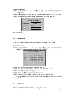
Page 11: ...gerprint Step 7 According to actual condition select yes or no If you select YES system will instruct you to place finger If you select NO system will inform the info input is successful 4 2 2 Add Super Password To add super password Step 1 In user management press key or key to move up and down and select add super password Press key System shows add new super password interface Step 2 Input supe...

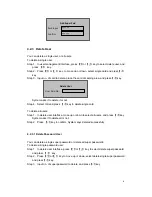
Page 12: ...ete all users Step 1 In delete user interface move up or down to select all users and press key System asks if to delete all or not Step 2 Press key to confirm System says deleted successfully 4 2 3 1 Delete Password User You can delete a single super password or delete all super passwords To delete a single password user Step 1 In delete user interface press or key to select delete super password...

Page 13: ...management interface by pressing or key to move up and down select add more master card and press key System prompt user to swipe the card Step 2 Place master card on swiping area and scan System prompts master card mode Step 3 Place card to add one by one at the swiping area to scan System says added successfully 4 3 A C 4 3 1 Period You can set unlock period including card swiping period holiday...

Page 14: ...erface Step 3 Press key or key select card swiping period and press key Step 4 Input time period and press key Input any number between 0 127 Screen displays period Step 5 Modify period and press key Step 6 Set other periods System asks if save it or not Step 7 Press key system asks if to save config or not Step 8 Select YES and press key System says saved successfully When new card set period 1 a...

Page 15: ... displays periods of Monday to Sunday Step 2 For example select Monday and press key Step 3 Config period press to select unlock mode of the period Step 4 Config Tuesday to Sunday periods Step 5 Press key System asks if save or not Step 6 Select YES and press key System says saved successful After completion A C unlock method will be managed according to the four periods 4 3 1 4 NO Period After us...

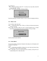
Page 16: ...2 Press key to delete old card no and input modified card no or directly place the card at swiping area for scanning and press key as follows System prompts setup is successful 4 3 3 Unlock Mode Unlock mode includes card password fingerprint card password card fingerprint card or password or fingerprint To set Step 1 In A C interface press or key to move up or down select unlock mode and press Ent...

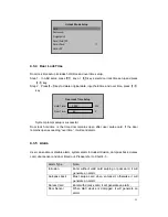
Page 17: ...send alarm 4 3 5 Alarm User can enable or disable alarm system alarm includes intrusion anti pass back duress card door sensor and door timed out Please refer to Chart 4 3 Alarm Type Note Intrusion Enter without valid card swiping or password it will generate an alarm Anti pass back Must swipe card when enter exit otherwise it will generate an alarm Duress Card Enter with duress card it will gener...

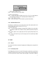
Page 18: ...select alarm to turn ON and press key as follows Press key again to close the alarm 4 3 6 Door Status Setup You can set A C status to normal NO or NC Step 1 In A C setup interface press key or key select door status setup and press key to enter door status setup interface Step 2 Press key or key select needed A C status and press key as follows After selection is successful a will shown next to do...

Page 19: ...p 3 Press key or key select date setup and press key Step 4 Input device date and device time and press key as follows System prompts setup is successful 4 4 1 2 Admin Password Change You can modify admin password Step 1 In local setup interface press or key select admin password setup and press key Step 2 Press key and key select date setup and press Step 3 Input old password press key as follows...

Page 20: ...erface press or select export all data and press key 4 4 1 5 Default To restore default settings Step 1 In local setup interface press or key select default and press key System asks if to restore or not Step 2 Select YES and press key to restore 4 4 2 Communication Setup It sets current access control communication Only IP for now Step 1 In system settings interface press or key select communicat...

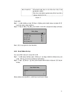
Page 21: ...In system setup interface press key or key select mode setup and press key Step 2 Select work mode and press Step 3 Press key or key select work mode and press key as follows After selection is successful a will be shown next to work mode 4 4 4 Reboot System To reboot the system Step 1 In main interface press or key select system reboot and press System asks if to reboot or not Step 2 Select YES a...

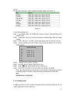
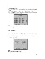
Page 22: ... 1 In system info interface press or key select alarm history and press key Step 2 Press or key user can view alarm history including alarm type alarm time and etc as follows Note Max can display 512 records of history Alarm History Alarm Type Alarm Time Duress 10 12 08 00 Door Sensor 10 12 08 43 Anti pass 10 12 08 36 Anti pass 10 12 08 43 Duress 10 12 08 45 Total 5 records Page 1 1 Card History T...

Page 23: ...e This manual is for reference only Slight difference may be found in user interface All the designs and software here are subject to change without prior written notice All trademarks and registered trademarks are the properties of their respective owners If there is any uncertainty or controversy please refer to the final explanation of us Please visit our website or contact your local service e...

Reviews: