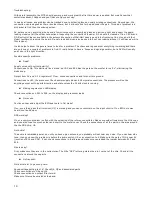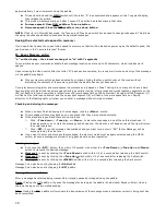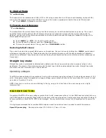
Through hole parts:
(use your normal solder {.02 or /.032} for most of these parts)
●
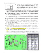
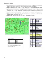
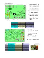
L14 – 8 turns on black T37-43 core. Wind now, but put aside and
install later.
10
●
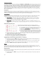
X1 – X5 tack solder case of X1,2, 3 and 4
to the pad along the top edge of the board.
A little blob of solder in between X1-X2 and
X3-X4 will do. Roughing up the edge of the
can with a small file can make the solder
stick to it easier.
●
Insert and solder the four (4) threaded
spacers into the corner holes and solder.
Insert from top side and solder on bottom.
●
X6 - tack solder top of crystal to solder pad.
●
Slide switches – these can go on either
side of the board, but the top side is
preferable.
●
S1-4 TACT switches. These can only go in
one way, so don't force them. The leads
which go along the top and bottom are
spaced a little farther apart.
●
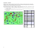
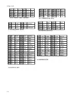
Through hole caps. Values shown in layout
locations are for 40 and 20 meter bands. If
another band combination is desired,
change values as needed. See table below
for value.
20M
40M
30M
C60
104 [0.1u]
C60
104 [0.1u]
C60
104 [0.1u]
C46, 56
151 [150 p]
C47, C57 331 [330 p]
C47, C57
221 [220p]
C51
331 [330 p]
C52
681 [680 p]
C52
561 [560p]
C65
22p [Orange] C66
68 p [Black]
C66
47p [Brown]
(C65/C66 already installed, values shown for reference if other band combination used)
●
C1, C20, C37 – 4.7 uFd electrolytic –
observe polarity, LONG LEAD PLUS.
●
C3 – 33 uFd electrolytic
●
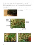
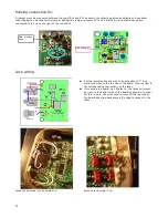
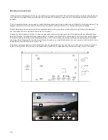
C59 – 100 uFd electrolytic – lay this part
over SMT components below Q5. See
photo below.
●
D4 – large glass diode – 47V zener.
●
Q7, Q8, Q9 - BS-170 TO-92
●
L4/8 L7/5 mount vertically.
●
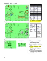
L10 to L13 See table below for inductor
values.
Location
20M
40M
30M
L5, L7
8.2 uH GRY/RED/GLD/GLD
------------------------------------------
-
-----------------------------------------
L4, L8
--------------------------------
18 uH BRN/GRY/BLK/GLD
12 uH BRN/RED/BLK/GLD
L10
T30-2 RED 11 turns 8”
--------------------------------------
----------------------------------
L11
T30-2 RED 15 turns 10”
--------------------------------------
------------------------------------
L12
-----------------------------------
T30-2 RED 16 turns 10”
T30-2 RED 13 turns 9”
L13
-----------------------------------
T30-2 RED 19 turns 11”
T30-2 RED 14 turns 10”
C 59 mounting
Summary of Contents for Mountain Topper
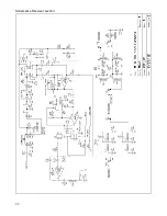
Page 22: ...Schematics Receiver section 22 ...
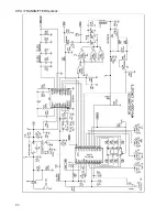
Page 23: ...CPU TRANSMITTER Sections 23 ...


