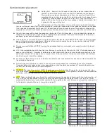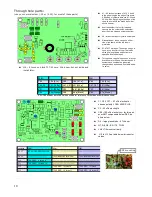
reference oscillator pins. Also check the soldering to the DDS chip.
Local Oscillator frequency trim and BFO adjustment:
This is used to trim the LO frequency to exactly match the center response of the IF crystal filter. This will ensure the best
sensitivity of the receiver. This adjustment is made with the help of an Oscilloscope. An audio spectrum analyzer program
running on your PC would also work. A program of this type is located on the CD. If one isn’t available, skip to step 5 and
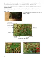
peak the BFO trimmer by ear. You can solder a short wire to TP2 and one of the headphone jack pins to hang a clip lead
onto.
NOTE: The default offset frequency comes out very close to ideal and likely will need no adjustment. The more important
adjustment is setting the BFO trimmer so that the beat note peaks in the audio filter response.
1. Connect a ‘Scope to TP2 (pin 1 of U3) ( 2V / div, 1 ms / div sweep)
2. Preset the BFO trimmer cap (CT1) by giving it about a ¼ turn.
3. You should hear a pretty loud tone in the headphones.
4. Repetitively click the Tune Down switch to step the LO frequency through the pass band of the filter. Note when the
signal at TP2 starts to decrease. Now start clicking the Tune Up switch and keep track of how many steps it takes
before the signal starts to decrease again. This tells you how wide the filter is. (Each click (step) tunes about 10 Hz.)
Divide the number of clicks by 2, then re-tune with the Tune Down switch that number of steps. The LO frequency will
now be set to the center of the pass band of the filter.
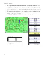
5. Move the input to the Scope to one of the headphone jack pins.
6. Adjust the green BFO trimmer cap, CT1, and peak the audio signal at the headphone jack. This centers the beat note in
the audio band pass filter.
7. Click the MENU button again to finish the calibration. The rig will reset and restart.
If the above calibrations worked, you know everything but the transmitter and filter boards are working properly. You can
now go onto the testing and adjusting the band filters. Otherwise, go to the trouble shooting guide on page and track the
reason the rig isn’t working down.
Receiver input peaking:
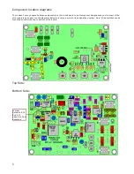
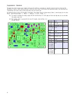
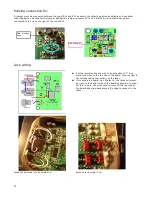
The two trimmers labeled “BNDB” peak the band selected with the slide switches set to the right. (normally 20 Meters).
Like wise, the two trimmers labeled “BNDA” peak the band selected with the switches set to the left (normally 40 Meters).
Attach an antenna or signal generator the antenna input and peak the trimmers for best signal or band noise. Note: the
receive can seem to be quite “deaf” until the trimmers are peaked. 20M may not have enough atmospheric noise to be
noticed, so finding a signal to peak or using a signal for an other transmitter maybe required.
Transmitter test and output (low pass) filter adjustment:
●
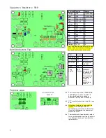
Connect a QRP watt meter and 50 ohm dummy load to the antenna jack
●
Connect a 9.0 Volt supply. Other voltages can be used, but power out at 9.0 volts is the only known data point for
sure.
●
Use a straight key or keep the Dash paddle closed when turning power to the board on so it goes into straight key
mode. This will be quicker then setting it into “tune” mode, which could also be done to get a steady carrier.
●
Key the transmitter and check the power output. If using a 9.0 volt supply, the power should be close to 2.5 watts
and between 4.5 and 5 watts with a 12.0 volt supply.
●
Power out can be tweaked by adjusting the spacing of the turns on the LPF toroids. Typically, moving turns closer
together on the coils on the PA side of the filter (L10 or L12) will decrease power while spreading them apart (to
be move evenly spaced around the core) will increase power. Adjusting L11 or L13 will have less effect, but can
influence the PA efficiency.
●
To achieve maximum PA efficiency, using an milliamp meter to monitor the current while making the filter
adjustments can allow you to find the point where you get the most power out with the least amount of current.
●
Once one band is done, switch to the other and make any adjustments if needed.
13
Summary of Contents for Mountain Topper
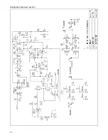
Page 22: ...Schematics Receiver section 22 ...
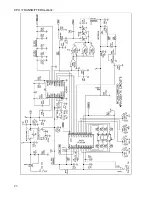
Page 23: ...CPU TRANSMITTER Sections 23 ...


