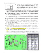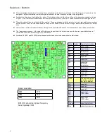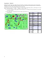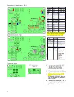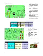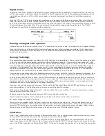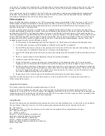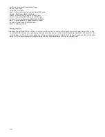
Troubleshooting:
With careful assembly, the MTR should power up and work great the first time power is applied. But we all know that
sometimes doesn't happen and you'll have to figure out why.
In nearly all cases, any problem can be tracked down to soldering issues, usually missing connections. On occasion, the
connection can look good as there is solder there, but it did not stick to the pad under the part. This kind of problem is a
bit harder to find then the missing solder.
So, before you do anything else, spend a few minutes with a magnifying glass and a strong light and inspect the board,
looking closely at all the solder connections. Inspecting the connections is easier if the board is cleaned of flux. CRC brand
QD Electronic Cleaner, available in the automobile section of Wal-Mart does a good job of removing flux. Use an old (but
clean) toothbrush to scrub the board. De-natured alcohol can also be used (do not use rubbing alcohol, it will leave a white
film residue).
It also helps to know the general area to look for a problem. The chances are good most everything is working and there
are only one or a couple of problems to find. It really helps to have a 'Scope and signal generator, but a DVM will usually
point you in the right direction.
Possible specific problems:
●
Dead!
Supply wired with correct polarity?
Connections to Q6. This part acts like a diode, but D2 and R24 bias the gate so the mosfet turns “on”, eliminating the
diode drop.
Output from 5V and 3.3 V regulators? If not, check connections and for shorts to ground.
Connections to U10, the processor. Check power supply pins and X6 crystal connections. The processor will not do
anything except set the ports direction and state unless the 32 kHz clock is running.
●
Missing segments on LED display.
Check connections on R31 to R38, on the display and processor leads.
●
No receive
Could you hear and adjust the BFO beat note in Cal mode?
If so, everything pass the first mixer (U3) is working and you can concentrate on the input circuits. If no BFO note was
heard, continue below:
DDS working?
If not, a common problem is often with the soldering of the reference oscillator. Make sure solder flowed into the little cups
and you didn't use too much solder and short to the metal cover. Check the connections of all the parts in the area around
the the DDS chip, U6.
Got Audio?
The audio is remarkably quiet, so until you hook up an antenna, you probably will not hear any noise. If you can hear side
tone, then you know the problem is before the audio switch, U9 or a connection to it. Make sure the gate of Q1 is near 5V
(junction of R14 and C36), if not, check connections in that area and make sure you added the jumper between R13 and
R14.
Mixers okay?
First, make sure they are in the correct way. The little “NXP” lettering marks the pin 1 corner of the chip. Check all the
connections around these parts.
●
No transmit:
Not a whole lot to go wrong here.
Keyed voltage getting to L14? Check Q4, Q5 and associated parts.
Check connections to U8 and L14
Check connections on output filter toroid.
Make sure filter values matches the band.
14
Summary of Contents for Mountain Topper
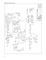
Page 22: ...Schematics Receiver section 22 ...
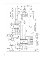
Page 23: ...CPU TRANSMITTER Sections 23 ...


