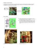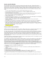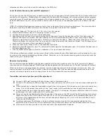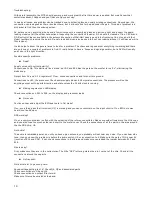
Operation:
Basic operation:
Turning the rig on and off:
As there is no power switch, the rig is turned on and off by inserting or removing the power plug from the jack. Make sure
the plug is firmly and fully inserted into the jack.
●
When the rig is powered up, it checks the position of the band select switch and loads the initial values for that
band. The display will flash a number to indicate the currently selected band (8, 4, 3 or 2) and annunciate that
number in Morse.
●
The initial frequency operating frequency will be the QRP calling frequency for that band as shown in the table
below. It is possible to change these default frequencies to another more to your liking later if you wish. Only two
of these bands are actually available for use, typically 40 and 20.
Band Display/Morse
Initial frequency
________________________________
40 M
4
7.030 MHz
30 M
3
10.118 MHz
20 M
2
14.060 MHz
Volume control:
There is none! Instead, an automatic level control is built into the rig. This circuit limits the audio output level to about 280
mV rms, which is about 5 mW into a 16 ohm load, typical for a pair of stereo headphones connected in parallel. With
sensitive ear buds, this can actually produce too much volume if your hearing is still good. In this case, an in line volume
control can be added in series with your headphones.
Band selection:
Three, DPDT switches are used to select one of the two bands the rig has been built for. Make sure all three switches are in
the same position, i.e., to the right or to the left.
●
The switch near the top edge of the case tells the processor which band is selected.
●
After switching bands, push one of the control buttons along the bottom edge of the case. This will “wake up” the
processor which then checks the current position of the band switch. A number indicating the band selected will
will flash on the display as that number is being annunciated by Morse.
●
When changing bands after initial power up, the last used frequency for that band will be loaded.
Control switches:
●
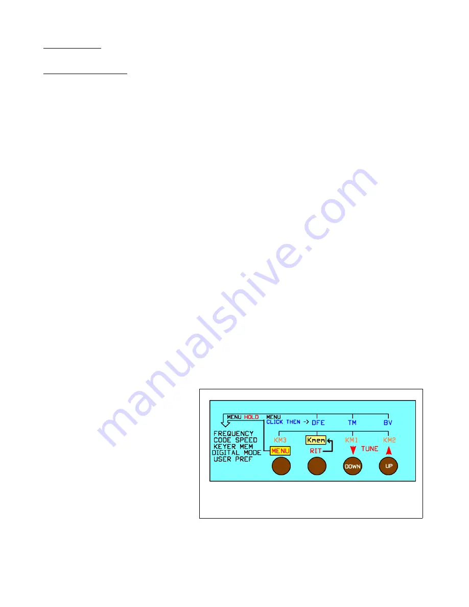
Four push button switches control the
operation of the Mountain Topper.
●
All switches have multiple functions.
The primary function of each switch is
labeled in red in the switch function
flow diagram shown to the right.
●
Secondary functions are enabled by a
short click of either the <
MENU
>
switch or the <
RIT
> switch, followed
by clicking the switch for the desired
function. This allows often used
secondary functions to be quickly
accessed.
●
Print out this page and cut out the
diagram to paste in the lid of your tin
as a reminder of switch functions.
17
Summary of Contents for Mountain Topper
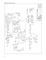
Page 22: ...Schematics Receiver section 22 ...
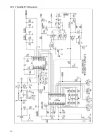
Page 23: ...CPU TRANSMITTER Sections 23 ...

