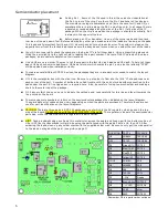
Assembly:
●
Your work area should be reasonably clean and uncluttered. Good lighting is a must.
●
Empty the packets containing the parts into small paper bowls. This will ensure that they do not get lost. Some
people like to do the assembly over a cookie sheet, as the lip around the edge helps to keep parts from going far.
The metal sheet also provides some measure of static control, especially if you ground it. A white sheet under
your work area could help in finding a part which might get away from you.
●
A very thin (0.015”) solder is supplied for soldering the surface mounted parts. Very little solder is need for each
connection. Ideally, you want a little convex fillet at the end of chip resistors and capacitors. Try not to end up will
a ball of solder at the end of the part.
●
Do not use liquid solder flux.
It simply makes a mess and is difficult to clean off the board and get out from under
parts. If not completely removed from the board, it can cause problems.
●
Before placing a part, lightly tin one pad for where it will go. You can speed assembly by tining one pad at all the
locations for which a particular value of part will go. There is no need for a low wattage soldering iron. It is best to
have a hot tip which will let you get the job done quickly. You will need a small tip on the iron, 1/32” to 1/16”
chisel or round is best.
●
Most of the surface mount parts come in part carriers. To remove the part(s), hold the carrier close to the work
surface and carefully peel back the clear plastic covering the part. This can be done with the tip of a sharp hobby
knife such as a #11 Xacto blade or pointy tipped tweezers. Once you remove the clear plastic strip, dump the
part out of the carrier and onto your work surface.
●
If you use tweezers to handle the parts, be very careful you don't grab onto them too tightly. These little parts
have a way of flying out from between the tips of the tweezers, never to be seen again. Apparently, they go into
the twilight zone, along with all the pens, small parts and hardware which falls off the bench. They must go
someplace since its never anywhere I can ever find them again!
●
An alternative to using tweezers to handle the parts is to use a tooth pick or chop stick with the end rubbed into
a little bees wax. The bees wax makes the end sticky so the part will stick to it. For the smaller IC's I grab them
length wise with the tweezers.
●
Tack the end of a part in its place by applying heat to the end of the part over the tined circuit board pad, while
applying a little pressure to make sure it lays flat to the board. Be sure to heat both the pad and the end of the
part. Generally, you will not have to add any additional solder to this connection. Then solder the other end of the
part. If you don't do this right away and go onto tacking down some more parts, there is a good chance you will
forget to go back and solder all the parts which require it.
●
It is nearly impossible not to make solder shorts between pins on the DDS chip, due to the close pin spacing.
Remove any shorts with solder wick.
Using solder paste:
Using solder paste is the ideal way to build the board. Small amounts of solder paste in an application syringe can be
bought for about $5.00 from Cash Olson over the internet. Also needed is a warming plate to preheat the board to about
200 degrees and a low power heat gun. An “Embossing” heat gun is commonly used (found at craft stores), though a hair
dryer on low setting might work. A soft air flow is required as to not to blow parts off the board.
A very small dab of solder paste is put on the pads and then the part placed over the pads. The parts will slide
around very easily, so one must be careful not to nudge them. The phono jacks and LED display should be hand soldered,
along with all the through hole parts. Start with the back side of the board with the most parts first.
Once all the parts have been placed, put the board on the warming plate and heat to about 200 degrees. Then
slowly heat the top of the board with the hot air gun. When the solder paste reaches its melting point, you will see it
liquefy and the parts snap into alignment to the pad. This is when the solder paste turns from a dull gray to shinny. Be on
the look out for “tomb stoning” which is when a chip cap or resistor will stand up on one end. Once all the solder has
reflowed, remove the power to the heating plate and let it cool down.
A video showing how to hand solder SMT parts and how to use solder paste can be found on the CD and is
viewable with Windows media player. The file is in the folder labeled “Video”
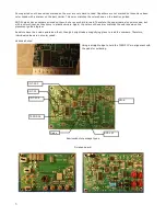
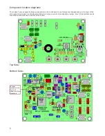
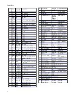
Using the parts placement guides:
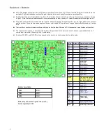
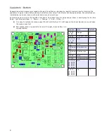
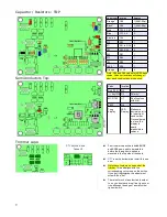
The parts placement guides on the following pages are color coded to show the location of the various parts. Parts which
are not yet to be installed or already have been installed are colored the same as the background color. The guides are
scaled so that the writing on them is easy to see on a computer monitor and come out crisper after the conversion to pdf.
Unfortunately, if you print all these pages out, it will use up a bunch of your ink jet ink.
2
Summary of Contents for Mountain Topper
Page 22: ...Schematics Receiver section 22 ...
Page 23: ...CPU TRANSMITTER Sections 23 ...


