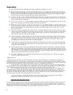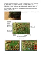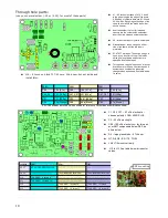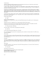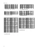
Resistors : Bottom
●
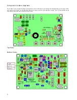
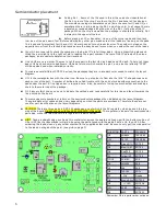
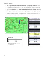
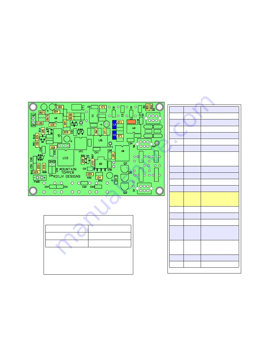
Since part designation numbers for most parts are not printed on the board, you will need to use the diagram to locate where the
part goes. Pay careful attention to where the part is located to be sure it doesn't go where a cap will go later.
●
Resistor locations are highlighted in yellow. The number shown inside the outline is the same as marked on body
of part.
Note that several resistors have four numbers printed on them, these a 1% values. Resistors with three digits are 5%.
●
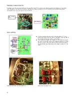
Three inductors will also be installed with the resistors. These are packaged with the resistors, but are larger and have no numbers
printed on them. There are two values used, so they are color coded. The two left over “orange” inductors will be used on the other
side.
●
There will be a number of resistors left over which go on the top side of the board. Put these aside in a safe place until needed.
●
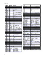
The “approximate location ” in the table will help locate the position of the resistor values on the board. upper/middle/lower is Y
coordinates area while left/center/right is X coordinates.
●
Resistors R3 (BS1) and R4 (BS2) values depend on the band to be used see band value table below.
7
Value
# places
Approximate location
471
1
upper/center
271
3
upper/center
222
2
lower/center
362
1
upper/center
103
5
upper/left
153
1
middle/left
223
5
middle/left
lower/left
lower/center
104
2
lower/center
224
1
middle/left
334
2
upper/left
105
1
upper/left
NOTE
The next two values
look alike – only the
last digit is different.
2671
1
upper/left
2673
1
upper/left
1133
1
upper/left
R3-
BS1
10K
1
upper/right
(20 M value)
R4-
BS2
47K
1
upper/right
(40 M value)
Orange 1
upper/right inductor.
Blue
2
middle/right inductor.
Band value table:
40M
47 K
30M
22 K
20M
10 K
BS1 (R3) should be highest frequency
band, typically 20 M
Summary of Contents for Mountain Topper
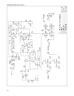
Page 22: ...Schematics Receiver section 22 ...
Page 23: ...CPU TRANSMITTER Sections 23 ...


