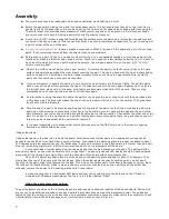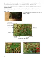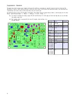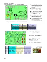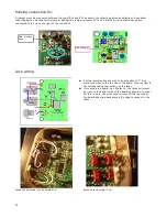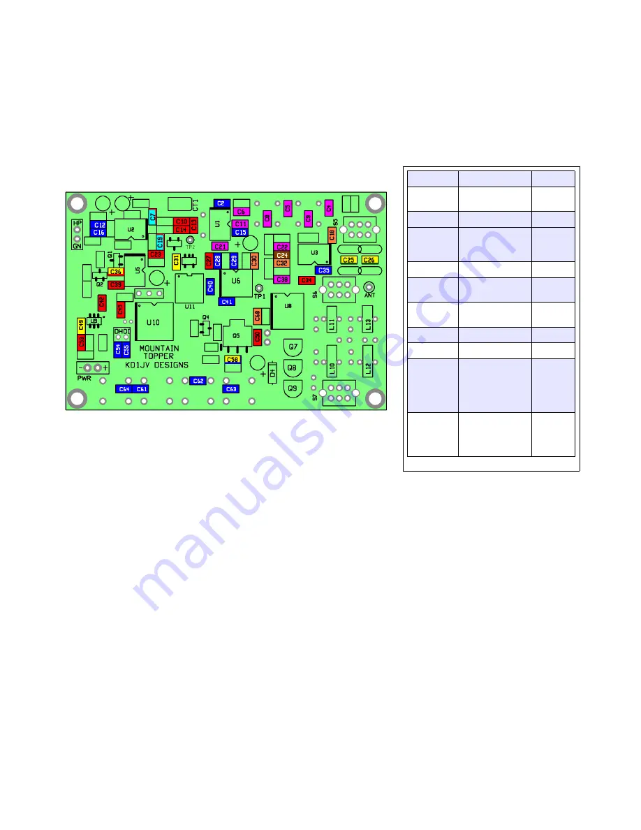
Capacitors : Bottom
Capacitors part carriers are color coded as the part its self has no markings to identify its value directly. Install all the
capacitors of a given value before starting to install another value. This will prevent mixing up values. Several values are
indicated by two colors, a main solid color and a second color stripe.
Several values are used on the top side of the board. Snip these from the strips and put them in a safe place for the time
being. light blue/red stripe – 1, Brown – 1, Orange – 1, Red – 3, Blue – 2.
●
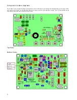
It is easy to confuse the orange caps (22 pfd) with the Red (0.1 ufd) caps on the layout digram, so we will pace
the orange ones first.
●
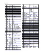
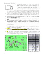
Part number start in upper left and run left to right, top to bottom in a
zig-zag fashion.
8
Location
color
# places
C18, 30,
32, 68
Orange
4
C25, 26
Yellow/green stripe
2
C4, 5, 6, 8,
9, 11, 21,
22, 38
Violet
9
C24
Brown
1
C58 (below
Q5)
Yellow/blue stripe
1
C36 (below
Q1)
Yellow/red stripe
1
C31, 49
Yellow
2
C7, C19
Light blue/red stripe
2
C2, 12, 15,
16, 28, 29,
35, 40, 41,
54, 55, 61,
62, 63, 64
Blue
15
C10, 13,
14, 23, 27,
34, 39, 42,
45, 50, 53
Red
11
Summary of Contents for Mountain Topper
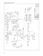
Page 22: ...Schematics Receiver section 22 ...
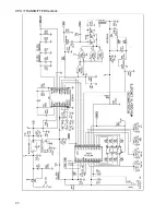
Page 23: ...CPU TRANSMITTER Sections 23 ...


