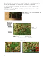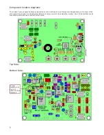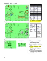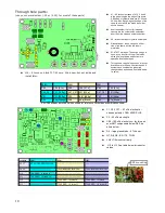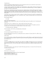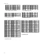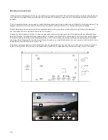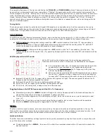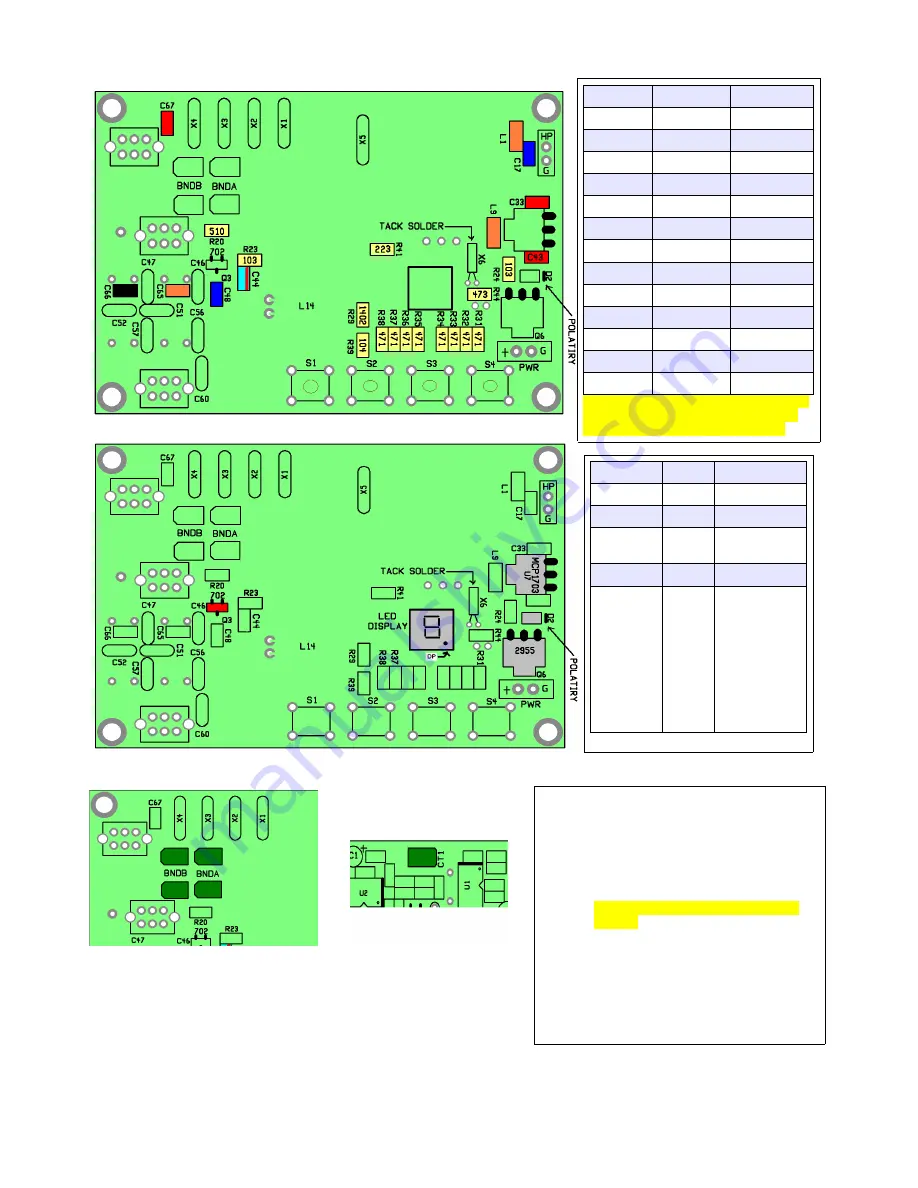
Capacitor / Resistors : TOP
Semiconductors Top:
Trimmer caps:
CT1 notched end
faces U1
9
Value/color location
#places
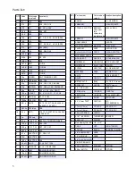
Orange*
C65
1 (20M- 22p)
Black*
C66
1 (40M- 68p)
Red
C33, 43, 67
3
Blue
C17, 48
2
Blue/red
C44
1
510
R20
1
471
R31 to R38
8
103
R23, R24
2
223
R41
1
473
R44
1
104
R39
1
1402
R29
1
Orange
L1, L9
2
*Note: C65 and C66 values for 40/20 band
combo. Values or locations will change if
other band combinations are desired.
Value
location
Red (702)
Q3
---- tiny! W8 D2
Polarity!
MCP1703
U7
Don't confuse
with Q6!
2955
Q6
7 seg
display
LED
Display
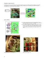
Make sure
decimal point is
in lower right
hand corner.
Once soldered
in place, the
display is
nearly
impossible to
remove.
●
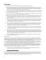
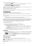
Four trimmer capacitors labeled BNDB
and BNDA now need to be installed
before the through hole parts are
mounted to the top side of the board.
●
CT1 is on the bottom side. Install this one
now.
●
Note the cut corners on one end of the
trimmer. This end aligns with the
corresponding cut corners on the outline.
If you get it backwards, the adjustment
screw will be “hot”.
●
There isn't much of a solder tab to solder
to, so you best have a real fine tip on your
iron, although the edge of a small chisel
tip could work.
Summary of Contents for Mountain Topper
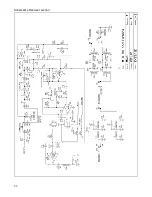
Page 22: ...Schematics Receiver section 22 ...
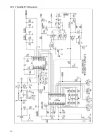
Page 23: ...CPU TRANSMITTER Sections 23 ...


