Installing the KE2 Therm Door Switch
Configuring Ethernet Enabled Controllers:
KE2 Evaporator Efficiency, KE2 Evap for Rack Efficiency & KE2 Controlled Environment
Configuring Non-Ethernet Enabled Controllers:
KE2 Low Temp & KE2 Adaptive Control
© Copyright 2017 KE2 Therm Solutions, Inc., Washington, Missouri 63090
Q.1.27 February 2017
Page 2
2.
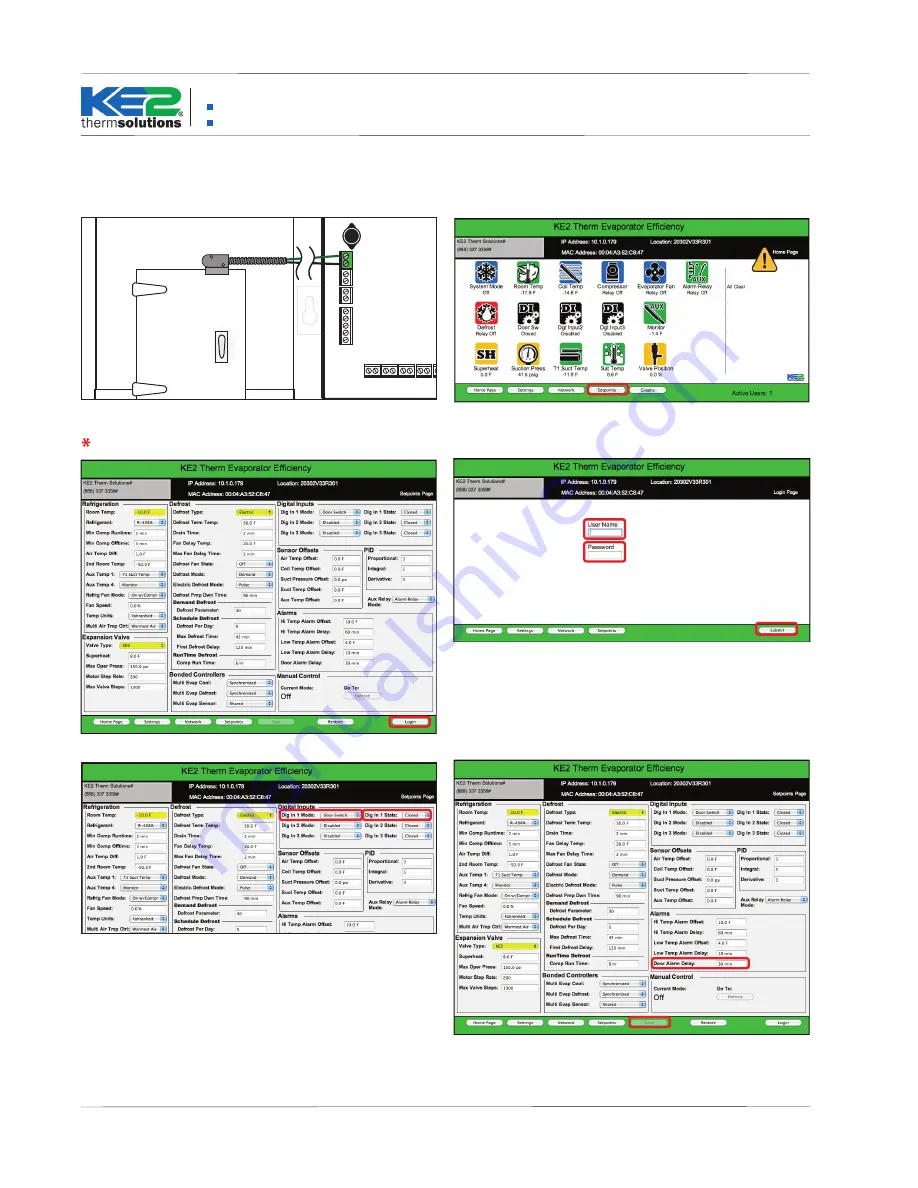
On the controller’s web page, select Setpoints from the Home Page.
3.
Select Login to make Setpoint changes.
4.
Enter the User Name ke2admin and the Password ke2admin* and
press Enter (Return) on your keyboard or click the Submit button on
the bottom right of the screen.
*For security purposes, the User Name and Password can be changed from
the factory default under the Settings Page.
5.
Set Digital Input Mode to Door Switch from the dropdown menu.
6
.
Set Digital Input State to active when Open from the dropdown
menu. Note: This can be set to Closed for a Normally Open door switch.
7.
Click Save.
8.
If the door is left open for the time set in Door Alarm Delay, an alarm
is activated and the system resumes cooling. Adjust the Door Alarm De-
lay based on your typical delivery timeframe.
Temperature Sensors Pressure
Transducer
T1Suct
T4Aux
T2Air
T3Coil
line
/
L1
ground
neutral
/
L2
NC
NO
NO NC
NO NC
COM
COM
NC
Power In
gr
een
re
d
black
NO
Transformer
3A Relay
3A Relay
COM
COM
COM
NC
NO
COM
NC
NO
18V
DI 1
DI 3
DI 2
Digital Inputs
1 2 3 4
+
_
*
Setting the KE2 Evap, KE2 Evap for Rack Efficiency, or KE2 Controlled Environment for use with a door switch.
1.
Wire door switch (dry contact) to a Digital Input.
(Further information
is found in Quick Start installation guide that shipped with the controller.)
Door switch wires may be extended.
NOTE: Screen shots shown are representative of the procedure. They will vary slightly based on the controller being installed, and
on the version of firmware. Any differences are irrelevant when installing a door switch.


