background image

© Copyright 2013 KE2 Therm Solutions, Inc., Washington, Missouri 63090

KE2 

Smart

Gate

Installation and Setup

Quick Start Q.5.24 July 2013

Page 4

First Use

The KE2 SmartGate ships pre-configured for use with the KE2 

Evaporator Efficiency controller. Port 1 is configured as a WAN 

port to be connected to either the customer’s existing network 

or their ISP’s (Internet Service Provider) supplied connection. 

The KE2 SmartGate is manageable by browsing to 10.10.255.254 

when plugged into port 2-10, or when wirelessly connected to 

KE2 WiFi.

Powering the KE2 SmartGate

The KE2 SmartGate is supplied with an attached transformer.  

The remote transformer accepts 100-240Vac incoming power.

Connecting the KE2 SmartGate

System Requirements

•  Internet Service is required for remote access

•  The KE2 Evap controllers must be physically connected with 

Ethernet cables

•  PC with Ethernet port or 802.11 wireless (B/G/N) 

•  Web browser (i.e. Chrome/Firefox/Internet Explorer/Safari)

Installation Environment

•  The  KE2  SmartGate  should  be  in  a  well-ventilated  location. 

Ensure device is not located near heat source

•  The KE2 Smartgate should not be in direct sunlight

•  Operating Temperature: -35°C to +60°C (-35°F to +150°F)

•  Operating Humidity: 10%-90%RH, Non-condensing

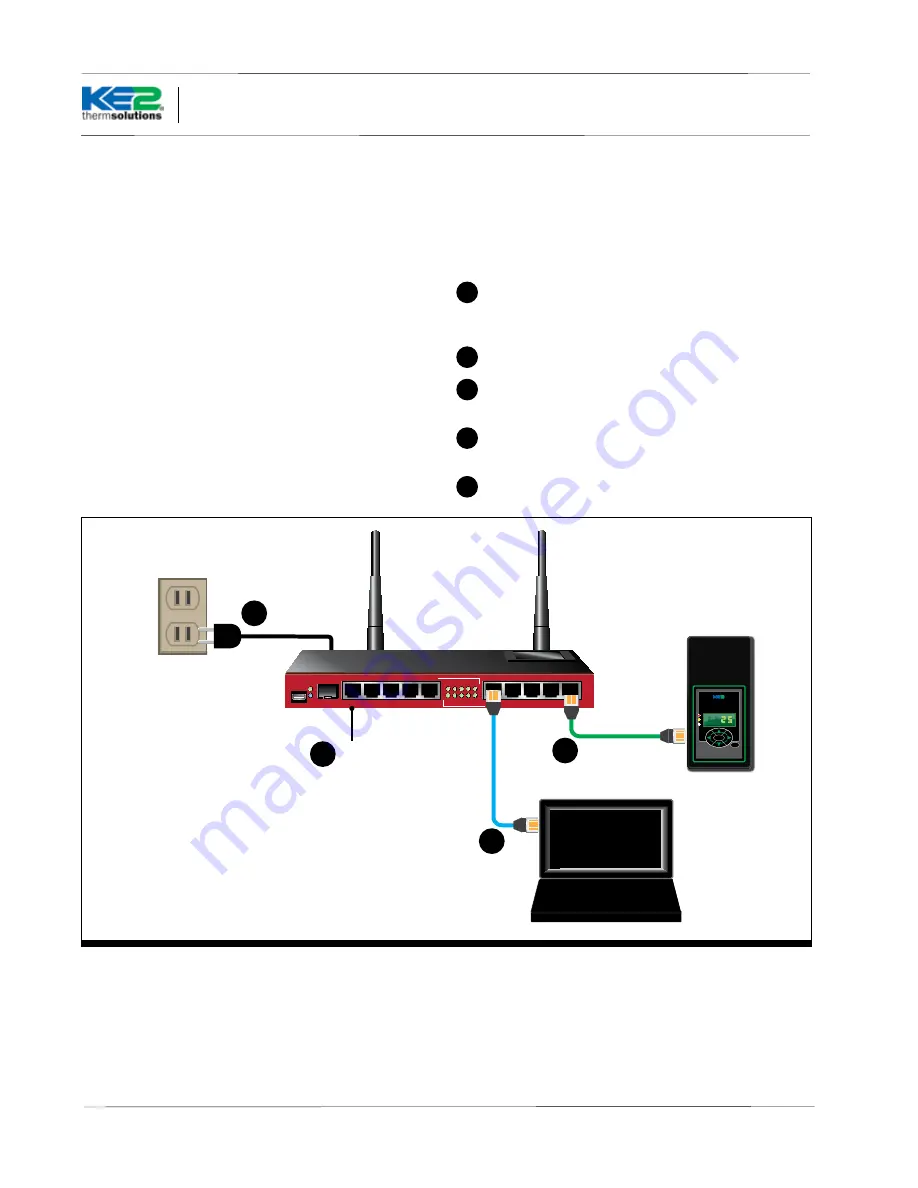
Connecting the KE2 SmartGate

a

Validate the PC’s Ethernet port and/or wireless is working 

properly by connecting it to the internet using the desired 

method prior to connecting to the KE2 SmartGate.

b

Ensure the KE2 SmartGate is powered.

c

Plug one end of the Ethernet cable into the PC and the other 

into one of the LAN ports on the KE2 SmartGate (Ports 2-10).

d

Connect the Internet service to Port 1, the WAN port. 

(Required for text/e-mail alerts and/or remote access)

e

 Connect to the KE2 Evap.

KE2 

Evaporator

Efficiency

therm

solutions

ENTER

BACK

RB201 1UAS-2HND-IN

USB

SFP

POE

GIGABIT ETHERNET

ETH1

ETH5

ETH3

ETH4

ETH2

ETH6

ETH10

ETH8

ETH9

ETH7

6   7   8   9  10

1   2   3   4   5

FAST ETHERNET

c

Internet 

Access

e

b

d

Summary of Contents for SmartGate

Page 1: ...or Commercial Refrigeration and AC Systems KE2 SmartGate Installation and Setup Q 5 24 July 2013 thermsolutions Powered by RB201 1UAS 2HND IN USB SFP POE GIGABIT ETHERNET ETH1 ETH5 ETH3 ETH4 ETH2 ETH6...

Page 2: ...e Refrigeration Network Using feedback from many field instal lations KE2 Therm s engineers have created the KE2 SmartGate The KE2 SmartGate natively provides the user with a powerful tool designed to...

Page 3: ...ss 802 11 B G N Expansion Fixed Gigabit Ethernet SFP cage USB MicroUSB powered POE ETH1 8 28v DC Antenna Gain 4dbi TX Power 30dBmDH thermsolutions Powered by RB201 1UAS 2HND IN USB SFP POE GIGABIT ETH...

Page 4: ...port or 802 11 wireless B G N Web browser i e Chrome Firefox Internet Explorer Safari Installation Environment The KE2 SmartGate should be in a well ventilated location Ensure device is not located ne...

Page 5: ...eded 1 To access the router s web inter face launch the web browser of your choice i e Chrome Internet Explorer Firefox Safari etc Enter the router s IP address 10 10 255 254 into the address bar of t...

Page 6: ...KE2 SmartGate the Quick Set tab will be automatically selected Changing the configuration from this page may cause the KE2 SmartGate to operate incorrectly Clicking the Reset Configuration should be a...

Page 7: ...ecific IP address provided by the local IT person nel or Internet service provider To change the KE2 SmartGate from a dynamic address to a static address move the radio button selection from DHCP to S...

Page 8: ...SmartGate s changing functionality It is for reference only NAT PAT Network and Port Address Translation are two techniques available to assist users in placing the KE2 Evaporator Efficiency Controll...

Page 9: ...t 18 Protocol 6 tcp 19 DST to the port used by the external IP address seleted by the user to access the KE2 Evap The Default port used by the KE2 Evap controller is TCP Port 80 In single controller a...

Page 10: ...age 10 Action Menu The setup should be as follows 20 Action dst nat 21 To Address this should match the KE2 Evaporator Efficiency s factory supplied IP address 22 To Port s this should always be port...

Page 11: ...new information Wireless Security 26 The KE2 SmartGate is protected with a custom pre shared key Users may change the password but must maintain the information for future access 25 26 27Wireless Clie...

Page 12: ...and date when connected to the Internet By default it is set to Central Standard Time To make changes to the settings 31Select System 32 Select Clock 33The time zone can be changed by clicking the arr...

Page 13: ...n MAC Server Netwatch Packet Sniffer Ping Ping Speed Profile SMS Telnet Torch Traceroute Traffic Generator and Traffic Monitor Note These are advanced topics and are beyond the scope of a typical Refr...

Page 14: ...to the bottom side of the device The password may be changed by the user if desired by selecting the Password option under the System tab 39They will then need to enter the current password Old Passw...

Page 15: ...Statistics 41The Interfaces tab displays a line for each connection with the information for each 41 VPN Configuration Now that the KE2 SmartGate is setup you can configure theVPN A To configure the...

Page 16: ...com KE2 SmartGate Installation and Setup KE2 SKU 20695 DEFAULT MANAGEMENT User admin Password A393A7Dc WIRELESS INFO ssid KE2SmartGate Psswrd WPA2PSK 753C4983a5f3 Serial 13092 015 VPN ACCOUNT CONTACT...

Reviews: