background image

7.8  Battery Temperature Probe Installation.


NOTE: If the probe is not connected, the UPS will continue to charge the batteries, but not optimize 

the DC voltage for temperature. 

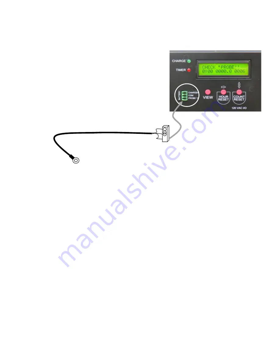
The MX includes a temperature probe that 

connects to one of the (+) post on the batteries. 

The (+) at the end of the string or where the total 

VDC is measured. 

Notice if the probe is not installed, the display will 

indicate (CHECK PROBE). This does not mean 

that the batteries will not charge. It is only to 

maximize the battery voltage during temperature 

fluctuations. 

Connect to VDC positive on the 

end battery string. Or to a 

battery surface with an adhesive 

20

DBL MX-U Series UPS Outdoors 1000-2000W 120V Manual English 

20180312


- This manual  is for qualified  personnel  only

Summary of Contents for DBL MX-U Series

Page 1: ...NCIDENTAL WHICH MIGHT ARISE OUT OF THE USE OF SUCH INFORMATION THE USE OF ANY SUCH INFORMATION WILL BE ENTIRELY AT THE USER S RISK AND C REMINDS YOU THAT IF THIS MANUAL IS IN ANY LANGUAGE OTHER THAN ENGLISH ALTHOUGH STEPS HAVE BEEN TAKEN TO MAINTAIN THE ACCURACY OF THE TRANSLATION THE ACCURACY CANNOT BE GUARANTEED APPROVED CONTENT IS CONTAINED WITH THE ENGLISH LANGUAGE D INFORMS YOU THE INFORMATIO...

Page 2: ...7 Section 5 UPS Working Principle Block Diagrams 5 1 5 2 UPS Systems Block Diagram 8 Operating Modes 9 5 3 UPS Audible Alarms 9 Section 6 Bypass Switch 6 1 6 2 HSU 1500 Bypass Switch 10 HSU 1500 Operation 11 6 3 Generator Bypass HSU Dual 12 6 4 Generator Bypass Operation 13 Section 7 Batteries Connections 7 1 This section left intentionally Blank 14 7 2 7 3 This section left intentionally Blank 15...

Page 3: ...ency 25 UPS Output Load Percentage 25 9 7 UPS Output Current 25 Battery Temperature Probe 20 9 8 9 9 Battery String Voltage 25 9 1 1 UPS Internal Surface Temperatue 25 9 1 2 Cold Starting The UPS Using The Batteries 26 10 1 UPS Latched Alarm 27 10 2 Procedure To Release The Latched Condition 27 10 3 UPS Default Parameters 28 10 4 Audible Alarm 28 10 5 Self Test 28 10 6 Bypass VAC Window 29 10 7 Ou...

Page 4: ...gramming Sreen 4 Battery VDC 34 Key Functions 34 Key Function Flashing Cursor 34 10 1 5 Changing The UPS Parameters 31 10 1 6 Turn OFF The UPS in AC Mode 32 10 1 7 Turn Off The UPS in DC Mode 32 10 1 8 Self Test Setting 32 10 1 9 UPS ECO Mode Setting 32 11 4 11 5 11 6 11 7 Section 12 UPS Relay Output Card 12 1 Pin assignment 35 12 2 EPO Emergency Power Off 35 Section 13 13 1 UPS Power Operational ...

Page 5: ...llow local or agencycodes The UPS is design to be installed in a properly vented enclosure To prevent overheating or over temperature always keep the cooling fans free from anyobjects that mayblock the UPS air intakes failure to do this will cause the UPS to over heat and shut down WHENINSTALLING THE UPS ENSURE THAT ALL THE CONNECTIONS AND GROUNDING PROCEDURESAREFOLLOWED A DISCONNECT DEVICE SHALL ...

Page 6: ...ital signal processing DSP also provides the UPS with powerful communication capability which simplifies remote control and monitoring 1 DBL MX U Series UPS Outdoors 1000 2000W 120V Manual English 20180312 This manual is for qualified personnel only Industry Leading A C input voltage range of 55 150 V allows under voltage or over voltage correction without unnecessary battery drain and helps exten...

Page 7: ... shipper and your distributor immediately The packaging is recyclable save it reuse it or dispose of it properly Remove the DBL MX U from its packing Check the contents for the following DBL MX UPS 1 Rack mount ears 2 AC harness assembly 1 DC battery preconfigured interconnect cable assembly 3 User Manual 1 Software disc and USB cable 1 ea EPO connector 1 2 DBL MX U Series UPS Outdoors 1000 2000W ...

Page 8: ...Section 4 4 1 Front Panel Views 3 DBL MX U Series UPS Outdoors 1000 2000W 120V Manual English 20180312 This manual is for qualified personnel only DBLMX1000U 48 DBLMX1500U 48 DBLMX2000U 48 ...

Page 9: ... the Programmable Outlet 1 Programmable Outlet 2 Amber LED lights up to indicate the Bypass Input is normal UPS Fault LED UPS On Alarm Silence UPS OFF Switch Special functions log in out Go to next page Go to previous page or change the setting of the UPS To re confirm the change of UPS Settings 4 2 UPS DISPLAY AND CONTROL PANELS DBL MX U Series UPS Outdoors 1000 2000W 120V Manual English 20180312...

Page 10: ... Site Wiring Fault 4 Buzzer Silent 5 UPS Overloading 6 UPS Working in specified mode 7 UPS Fault or Abnormal Warning 8 UPS Flow Chart 9 3 Digit Measurement Display 10 Indicates the item to be measured 11 Battery Abnormal 12 Battery Low 13 Testing 5 DBL MX U Series UPS Outdoors 1000 2000W 120V Manual English 20180312 This manual is for qualified personnel only ...

Page 11: ...isplay 2 3 Button Programming set scroll next 3 Charge Status LED 4 Timer Function LED 5 Timer Counter Hours 6 TempProbe Connector 5 4 1 3 2 6 6 DBL MX U Series UPS Outdoors 1000 2000W 120V Manual English 20180312 This manual is for qualified personnel only ...

Page 12: ...g systems including Windows 98 Me NT 2000 2003 XP Vista 2008 7 8 Novell NetWare Unix Linux 2 6 x Mac OS X v10 5 Leopard Mac OS X v10 6 Snow Leopard please contact your local dealer for suitable software All communication ports including optional cards can be active and used simultaneously to monitor the UPS status However only one communication interface at a time the one with the highest priority...

Page 13: ...l circuit 2 A DC to AC high frequency inverter 3 An intelligent battery charger 4 A bank of stationary maintenance free batteries 5 A DC to DC push pull converter control circuit 6 A static bypass loop 7 Input and output EMI filters Section 5 5 1 UPS System Block Diagram 8 DBL MX U Series UPS Outdoors 1000 2000W 120V Manual English 20180312 This manual is for qualified personnel only ...

Page 14: ...harger stop operating Battery discharges via DC DC boost circuit and supplies Inverter Alarm buzzer beeps quickly indicating battery power low and Inverter may stop supplying soon LED off and LEDs illuminated 5 3 Audible Alarm Codes The following table contains common UPS statuses with their Audible Alarm codes UPS Status Audible Alarm Code UPS faulty Inverter shut down All functions inhibited Lon...

Page 15: ...s 5 conductors Please make note each conductor has a specific function If the conductors are not connected correctly damage to the UPS and Bypass may occur Black This is the Utility Input Source White These 1 or 2 are Neutrals for the Utility Input and UPS output they are always common Red This is the UPS Output Line LOAD Green This is the UPS and Bypass Grounding conductor Bypass AUTO Line Availa...

Page 16: ...e is a power failure the Equipment will not be backed up or protected 6 3 AUTO Position UPS Operating 1 The Bypass is equipped with 4 LEDs that will indicate the Status of the switch 2 The rocker switch should be placed in the AUTO position 3 The GREEN UPS ON LINE LED will be ON 4 In this position the AC Utility travels to the UPS UPS TURNED ON then from the UPS through the BYPASS directly to the ...

Page 17: ...CONNECTOR UPS to BYPASS Line Available Bypass UPS On Line UPS Available Line Available Bypass UPS On Line UPS Available MOLEX BLACK AC INPUT WHITE AC INPUT NEUTRAL RED UPS OUTPUT TO LOAD G WHITE AC OUTPUT NEUTRAL BROWN ORANGE GENERATOR WHITE GENERATOR NEUTRAL 12 DBL MX U Series UPS Outdoors 1000 2000W 120V Manual English 20180312 This manual is for qualified personnel only ...

Page 18: ...rator section controls the source of alternate power being directed to the UPS In the Auto Position the alternate source of power is automatically selected If there is Utility power present and generator power is applied the Utility power will always be used the switch will not transfer to generator During a power failure the UPS will operate on Battery if a generator is connected the switch will ...

Page 19: ...SECTION 7 7 1 This Section Intentionally Left Blank 14 DBL MX U Series UPS Outdoors 1000 2000W 120V Manual English 20180312 This manual is for qualified personnel only ...

Page 20: ...7 2 This Section Intentionally Left Blank 15 DBL MX U Series UPS Outdoors 1000 2000W 120V Manual English 20180312 This manual is for qualified personnel only ...

Page 21: ...16 7 3 48 VDC Battery Cables DBL MX U Series UPS Outdoors 1000 2000W 120V Manual English 20180312 This manual is for qualified personnel only 30 cm A B C D ...

Page 22: ...figuration 48VDC MX 1000U 48 1500U 48 2000U 48 Layout View of the 48VDC Battery Harness 48 00 17 DBL MX U Series UPS Outdoors 1000 2000W 120V Manual English 20180312 This manual is for qualified personnel only A B C D ...

Page 23: ...7 5 This Section Intentionally Left Blank 7 6 This Section Intentionally Left Blank 18 DBL MX U Series UPS Outdoors 1000 2000W 120V Manual English 20180312 This manual is for qualified personnel only ...

Page 24: ...7 7 This Section Intentionally Left Blank 19 DBL MX U Series UPS Outdoors 1000 2000W 120V Manual English 20180312 This manual is for qualified personnel only ...

Page 25: ...the end of the string or where the total VDC is measured Notice if the probe is not installed the display will indicate CHECK PROBE This does not mean that the batteries will not charge It is only to maximize the battery voltage during temperature fluctuations Connect to VDC positive on the end battery string Or to a battery surface with an adhesive 20 DBL MX U Series UPS Outdoors 1000 2000W 120V ...

Page 26: ...erminations must be tight and correct Always use the Red Conductor for the Load Protected side The Black Line is always used for the Utility side Always Follow the correct grounding procedures The DBL MX is supplied with an AC Anderson 6 pole latching and a D C Anderson 4 Pole latching connector assembly Both ends of the A C harness are exactly the same and reversible 1 You will notice Black with ...

Page 27: ...00U 48 use 4 battery in Series for a total of 48VDC After the batteries have been connected it is good practise to always verify the DC voltage using a Digital Multi meter before connecting to the UPS Insert the DC 4 pole connector until it is fully seated The DC uses a resetable breaker or internal fusing Place the switch to Bypass position Section 9 0 will cover the Start Up of the UPS when all ...

Page 28: ...in the start sequence for 5 seconds The LCD display now indicates the measured input VAC 9 LEDs will light up to indicate that the Utility and the Bypass are normal 10 Then the AC input Icon and outputs icons 1 2 LEDs will remain on These 3 icons indicate the presence of AC Input voltage and output voltage The UPS has two internal outputs that are in use 1 2 Power Flow Input Power Flow Out The abo...

Page 29: ...after start up or in a normal operating mode Use the select down key The display sequences are as follows Figure F AC input voltage Figure G AC input frequency 24 9 3 9 4 9 5 Output Voltage DBL MX U Series UPS Outdoors 1000 2000W 120V Manual English 20180312 This manual is for qualified personnel only ...

Page 30: ...ing percentage Figure K UPS output current Figure L Battery String voltage Figure M UPS inner temperature in C 25 9 6 9 7 9 8 9 9 9 1 1 DBL MX U Series UPS Outdoors 1000 2000W 120V Manual English 20180312 This manual is for qualified personnel only ...

Page 31: ...indicate the power flow Notice that the INPUT has a block around the word and the reading is 0 Scroll using the down or up button to read the output VAC Current Load DC voltage etc Load may be connected to this UPS before the cold start or after To Shut down the UPS press and hold the OFF button and listen for the Audble beeps then release Note The DC Voltage will decline in this state of operatio...

Page 32: ...o allow the UPS to function normally The LCD will display an alarm code Notice the Triangle Icon in RED UPS LOAD INPUT Code 10 2 The procedures used to release the UPS from the locked up status are below a b c d e f Check and record the error code Check user s manual to understand possible cause solve the problem or call service provider Press OFF key and hold for 5 seconds until there is an audib...

Page 33: ...lf test This the Self Test function of the UPS It may be set to off so that the MX U will perform an Auto test Press the scroll up key to execute the special functions The functions include buzzer ON as in figure Q1 buzzer OFF as in figure Q2 Alarm silence for UPS Warning and self test OFF as in figure R1 or self test ON as in figure R2 The UPS will execute the battery test for ten seconds 28 10 4...

Page 34: ...onization Window This is a function that operates in conjunction with the above settings This is the ideal setting This is the actual measured output voltage provided by the UPS The Indicate the operations Standard and Service mode of the UPS This indicates that the UPS is operating in a Economy mode and is operating in an energy saving mode 29 10 6 10 7 10 8 10 9 10 1 1 DBL MX U Series UPS Outdoo...

Page 35: ...ent 3 2 1 0 1 2 3 Figure W Output Voltage Fine Tune Values The UPS is converting the frequency to 50Hz from 60Hz mode The UPS is converting the frequency to 50Hz to 60Hz mode 30 10 1 2 10 1 3 10 1 4 DBL MX U Series UPS Outdoors 1000 2000W 120V Manual English 20180312 This manual is for qualified personnel only ...

Page 36: ...ry default If there is a special application please call the factory Figure T indicates the bypass frequency window of the Inverter Output The acceptable setting values are 3 Hz and 1 Hz It is best to leave this at the factory settings If the application requirements are such that this needs a change always call the factory Figure U indicates the acceptable Inverter Output Voltage Possible values ...

Page 37: ...able for UPS work in ECO or Inverter mode The ECO Mode will increase the effeciency of the UPS to an amount of 96 This mode will introduce a switching mode where as the inverter will be used only when the UPS sense that the voltage is out of a range and requires the batteries for power The voltage regulation will be minimized when the ECO mode is used This will not affect the ability of the UPS to...

Page 38: ...atus Battery bank voltage and Battery temperature monitor Temperature compensating isolated Charger control signal LED Charge Status Indicator Timer Output Low Battery Output 11 2 LED Functions Led Functions Led Colour Led Full On Led Flashing Led Blip Charge Green Full Charge Charging Battery Red Low Batt Alarm Low Batt Warn Discharging 11 3 Display Screens Scr 1 1st Line 2nd Line Titles Status M...

Page 39: ...y Scroll to next Clear Accum Hrs Clear Events Scr 2 Program Timer Scroll to next See below See below Scr 3 Instrument Display Scroll to next none none Scr 4 Program Low Battery Scroll to 1st screen See below See below 11 8 Key Functions Program Screens flashing cursor Key All screens ProgramScreens View Scroll screens After Incr Key restore previous Next After Incr Key accept new value Incr Increm...

Page 40: ...e UPS is operating normally 12 2 EMERGENCY POWER OFF WITHOUT VOLTAGE This is small Phoenix Green connector that is inserted in the receiver receptacle located on the front of the UPS just below the USB port This small Green 2 pole connector is inserted into the UPS The EPO only requires dry contact closure N C The UPS will shut down including the ability to supply output power to any type of load ...

Page 41: ...verter to bypass output when there s an overload or when there s UPS abnormality i UPS output EMI Filter Suppresses the electromagnetic interference signal at the UPS output side to avoid mutual interference between the load and UPS j UPS output power Provides stable AC power needed for the load k Charger Charging device for the battery l Booster Boosts the battery voltage to the DC voltage needed...

Page 42: ...heck and verify battery QTY Max 6 x 55AH without ext ABM How old are the batteries Has there been a power failure For faster recharge install ABM Before discharge test If the battery voltage is lower than 12 5nV the UPS will cease the self test right away and show error code alarm Check and verify battery QTY Max 6 x 55AH without ext ABM How old are the batteries Has there been a power failure For...

Page 43: ...or the vents must be available for adequate ventilation Replace the fan Line Displays error code alarm Switch to bypass for 1 line minute then back to Inverter UPS must decrease internal heat Clean the UPS Check the fan How long has the UPS been in service 6 of space for the vents must be available for adequate ventilation Replace the fan Er12 Inverter overload Line Displays error code alarm Switc...

Page 44: ...tery voltages What is the age of the batteries Has there been a long power failure Add ext ABM Er21 Reserved Er22 23 Reserved Er25 Reserved Er26 Input Over Current Bypass abnormal or CVCF Show error code alarm then switch to bypass mode After 1 minute it switches back to the Locks the UPS then show error code alarm Maximum 6 x 55 AH Check and test battery voltages What is the age of the battery s ...

Page 45: ...s function can not be activated if the charger is OFF position Shut down the UPS disconnect the AC Install batteries that are fully charged Restart the UPS P S 2 Low Battery Initial Start Up When the UPS is on DC START but the battery Initial voltage is less than 11 2nV the UPS will turned off automatically Check and verify battery voltage Verify the age of the batteries Has there been a power fai...

Page 46: ...il low battery warning Frequency Synchronized Range 3 Hz or 1 Hz selectable Frequency Battery Mode 50 60 Hz 0 2 unless synchronized to line Current Crest Ratio 3 1 Voltage Harmonic Distortion THDv 3 at full linear load 7 at full non linear load Voltage Regulation 1 Dynamic Stability 60ms 5 10 to 90 Load Output Waveform Pure sine wave Outlets 1x Terminal 2x NEMA 5 15R AC Inverter Supply 105 continu...

Page 47: ... Site Wiring Fault Fault Overload and Load Battery Level Programable timer 100 hr delay Battery Temp Probe Low battery setting relay etc 6 Button ON Silence OFF Enter Function UP Down Audible Alarms Battery Mode Sounds once every 1 5 seconds Low Battery Sounds once every 0 2 seconds Overload Sounds once every 3 seconds Normal alarm Sounds once every 3 seconds Fault Continuous tone Protection Short...

Page 48: ...nsation Interface Communications Standard RS 232 EPO Relay Contact Board Timer Relay Fault Relay Low Battery Relay Optional SNMP Ethernet Compatible Platforms Microsoft Windows series Linux Mac etc Standards And Certifications Safety cTUVus EMC FCC Part 15 Class A FCC 43 DBL MX U Series UPS Outdoors 1000 2000W 120V Manual English 20180312 This manual is for qualified personnel only ...

Page 49: ..._____QTY Of Batteries__________ Type Of Battery ________________ AH Rating Of Batteries ________ ABM QTY _____________ Test each battery under the following UPS operating conditions BAT 1 BAT 2 BAT 3 BAT 4 Batteries Disconnected UPS OFF Batteries Connected UPS ON No Load Batteries Connected UPS ON with load String VDC DC Cold Start Batteries Connected UPS ON No Load DC Cold Start Batteries Connect...

Page 50: ...considerably faster then good batteries If the battery or batteries are weak the UPS may alarm during the test All of the batteries in the string should be changed if a battery has not passed this test If the batteries have all passed the testing and the batteries are not equal the batteries should be removed from the string and charged individually Or a battery ABBM battery balancer should be ins...

Reviews: