KE 4256-3230 Keatec T Series UPS 10-40K 380Vac Users Guide English 20170126 This manual is for qualified personnel only.
Page 13
Make sure each UPS input breaker is in the “off” position and there is no output from any of the UPS.
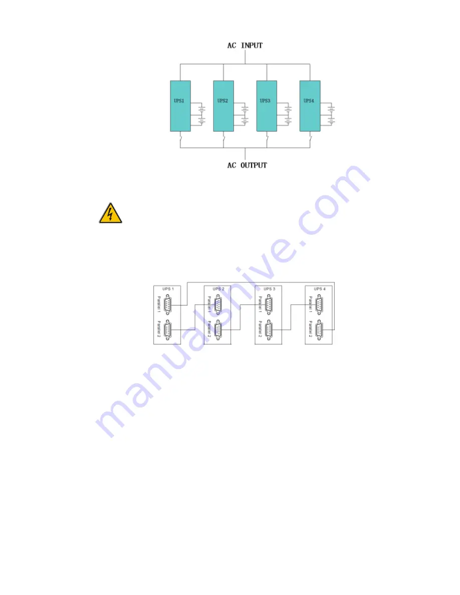
Battery groups can be connected separately or in parallel, which means the system can be either
a separate battery or a common battery.
WARNING!
Make certain the N, A (L1), B (L2), C (L3) lines are correct and grounding is
well secured.
3.9.2 Parallel cable installation
The shielded and double insulated control cables must be interconnected in a ring configuration
between UPS units as shown below. The ring configuration ensures high reliability of the control.
3.9.3 Requirement for the parallel system
For a group of paralleled modules behave as one large UPS system and in order to assure that
all modules are equally utilized and comply with relevant wiring rules, follow the requirements
below:
1)
All UPS must be of the same rating and be connected to the same bypass source.
2)
The Bypass and Mains input sources must be referenced to the same neutral potential.
3)
The outputs of all the UPS modules must be connected to a common output bus.
4)
The length and specification of power cables including the bypass input cables and the
UPS output cables must be the same. This facilitates load sharing when operating in
bypass mode.
3.10 Computer access
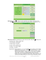
To use the included software management program Muser4000 a USB connection is required.
One end of an USB cable connects to the computer and the other end connects to the USB port
on the UPS.
◆
Open the Muser4000 software, then click on the “system” button.


