background image

1-800-KEATING

www.keatingofchicago.com

Users Manual

MIRACLEAN

®

GAS GRIDDLE

SERIES 2000

READ AND SAVE THIS MANUAL FOR FUTURE REFERENCE.

Keep this manual for training new personnel.

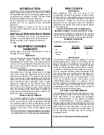
INTRODUCTION  . . . . . . . . . . . . . . . . . . . . . . . . . . . . . . . . . . . . . . . . . .1

INSTALLATION INSTRUCTIONS

 . . . . . . . . . . . . . . . . . . . . . . .1

DAMAGE IN SHIPMENT  . . . . . . . . . . . . . . . . . . . . . . . . . . . . . . . . . . .1

POSITIONING  . . . . . . . . . . . . . . . . . . . . . . . . . . . . . . . . . . . . . . . . . . . .1

VENTILATION  . . . . . . . . . . . . . . . . . . . . . . . . . . . . . . . . . . . . . . . . . . . .1

NATIONAL CODE REQUIREMENTS  . . . . . . . . . . . . . . . . . . . . . . . .1

GAS CONNECTIONS AND PIPE SIZE  . . . . . . . . . . . . . . . . . . . . . .2

FLEXIBLE GAS CONNECTIONS & QUICK

DISCONNECT DEVICES  . . . . . . . . . . . . . . . . . . . . . . . . . . . . . . . . . .2

LEVELING  . . . . . . . . . . . . . . . . . . . . . . . . . . . . . . . . . . . . . . . . . . . . . . .2

STAND ASSEMBLY  . . . . . . . . . . . . . . . . . . . . . . . . . . . . . . . . . . . . . . .3

LIGHTING INSTRUCTIONS  . . . . . . . . . . . . . . . . . . . . . . . . . . . . . . . .4

SHUTDOWN  . . . . . . . . . . . . . . . . . . . . . . . . . . . . . . . . . . . . . . . . . . . . .4

COOKING  . . . . . . . . . . . . . . . . . . . . . . . . . . . . . . . . . . . . . . . . . . . . .4-5

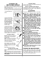
CLEANING . . . . . . . . . . . . . . . . . . . . . . . . . . . . . . . . . . . . . . . . . . . . . . .6

PREVENTIVE MAINTENANCE

 . . . . . . . . . . . . . . . . . . . . . . .6-7

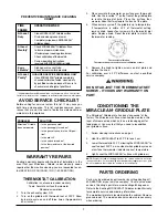
AVOID SERVICE CHECKLIST  . . . . . . . . . . . . . . . . . . . . . . . . . . . . . .7

CLEANING CARE & CONDITIONING  . . . . . . . . . . . . . . . . . . . . . . .7

THERMOSTAT CALIBRATION  . . . . . . . . . . . . . . . . . . . . . . . . . . . . . .7

SERVICE PARTS ORDERING . . . . . . . . . . . . . . . . . . . . . . . . . . . . .7-8

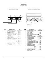
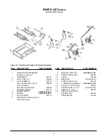
PARTS LIST  . . . . . . . . . . . . . . . . . . . . . . . . . . . . . . . . . . . . . . . . . . . . . .8
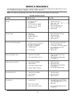
SERVICE DIAGNOSIS

TROUBLE SHOOT CHART  . . . . . . . . . . . . . . . . . . . . . . . . . . . . . . .10

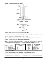
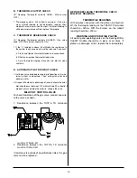
THERMOSTAT REMOVAL & REPLACEMENT . . . . . . . . . . . . .11-12

SERVICE  . . . . . . . . . . . . . . . . . . . . . . . . . . . . . . . . . . . . . . . . . . . .11-13
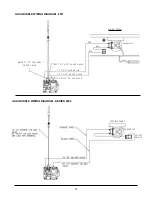
WIRING DIAGRAM

 . . . . . . . . . . . . . . . . . . . . . . . . . . . . . . . . . . .14

CONTENTS:

IMPORTANT:

Keep a copy of your bill of sale. The date on the bill establishes the warranty period should

service be required. If service is performed, it is in your interest to obtain and keep all receipts. Keating 
commercial griddles are not intended for household use.

The Owner’s Guide provides specific operating instructions for your model. Use the Miraclean

®

Gas

Griddle only as instructed in this Owner’s Guide.

g a s G r i d d l e 2 0 0 0

0 2 / 1 3

p a r t #   0 373 9 9

RECORD THE MODEL AND SERIAL 

NUMBERS OF THIS MIRACLEAN

®

GAS 

GRIDDLE IN THE SPACES PROVIDED.

SERIAL NO. ______________________________

MODEL NO. _____________________________

KEEP THESE NUMBERS FOR FUTURE REFERENCE.

*AS CONTINUOUS PRODUCT IMPROVEMENT OCCURS, SPECIFICATIONS MAY BE CHANGED WITHOUT NOTICE.

Summary of Contents for SERIES 2000

Page 1: ...UBLE SHOOT CHART 10 THERMOSTAT REMOVAL REPLACEMENT 11 12 SERVICE 11 13 WIRING DIAGRAM 14 CONTENTS IMPORTANT Keep a copy of your bill of sale The date on the bill establishes the warranty period should...

Page 2: ...AY EVENTUALLY LOSE ITS ODOR AND PRECAUTIONS SHOULD BE TAKEN TO ASSURE THAT PROPANE GAS IS NOT PRESENT EVEN THOUGH YOU DO NOT DETECT AN ODOR IF THERE IS ANY DOUBT YOU SHOULD CALL YOUR LOCAL PROPANE GAS...

Page 3: ...T RETURN DAMAGED MERCHANDISE TO KEATING FILE YOUR CLAIM AS ABOVE FIRST STEPS POSITIONING Keep appliance area free and clear of any combustibles Position the Miraclean Griddle 6 inches 152mm from any c...

Page 4: ...ure Refer to serial plate for proper gas requirement for your particular model FLEXIBLE GAS CONNECTORS AND QUICK DIS CONNECT DEVICES For an appliance equipped with casters The installation shall be ma...

Page 5: ...te to determine if the burner is set up for the proper type gas before connecting the quick disconnect or piping from the building gas supply pipe a Gas pressure at manifold NATURAL GAS 4 0 in W C b G...

Page 6: ...fers conducted heat to the food being cooked more rapidly than other griddle plates because the food is placed directly on the metal surface It is the understanding of this rapid heat transfer that pe...

Page 7: ...nventional griddles at least start at lower tem peratures You may be able to work the tempera ture up as you become accustomed to the more rapid cooking of the Miraclean Griddle 2 Cook as usual but af...

Page 8: ...an surface is very hard With proper care the MIRACLEAN surface and its unique cooking prop erties will last for many years Damage done to the Miraclean surface is irreplacable NEVER USE A GRIDDLE STON...

Page 9: ...ition your griddle surface 1 Follow cleaning instructions on page 5 2 Heat the MIRACLEAN to 400 F for one hour 3 Lower thermostat to 350 F allowing the MIRACLEAN to cool to about 350 F as is evident w...

Page 10: ...GAS VALVE 004803 11 SCREW FOR TAN KNOB 004805 NOT SHOWN ITEM DESCRIPTION P N 1 CONTROL PANEL INSERT 1 800 KEATING 2 DIAL PLATE 200 500 F 060105 3 THERMOSTAT 550 F 023897 THERMOSTAT KNOB BLACK 038368...

Page 11: ...INSERT REFERENCE ONLY 6 BURNER REFERENCE ONLY 7 AIR SHUTTERS 031477 8 MAIN SUPPLY GAS VALVE 3 4 not shown above ITEM DESCRIPTION PART NUMBER 9 MAIN GAS PIPE 3 4 REFERENCE ONLY 10 STREET ELBOW 3 4 0057...

Page 12: ...is in pilot position c Thermostat is not turned on d Low gas presssure e Gas valve failure a Put ON OFF switch to ON position b Turn knob to ON position c Turn thermostat to desired temperature d Set...

Page 13: ...T 1 Lower the control panel by removing the screws 2 Disconnect the wires on the switch and remove switch 3 Snap the new switch into place and reconnect all wires 4 Return the control panel to its nor...

Page 14: ...1000MV range Conduct each check below by connecting meter test leads to terminals as indicated All readings are closed circuit A BURNER COIL CHECK A Reading Thermostat contacts CLOSED Gas Valve knob...

Page 15: ...mum output is observed Then extinguish pilot and observe meter 2 Dropout of automatic pilot magnet sound should be audi ble should occur between 120 millivolts and 30 millivolts If dropout occurs outs...

Page 16: ...GRIDDLE WIRING DIAGRAM SERIES 2000 CONTROL PANEL THERMOSTAT ON OFF SWITCH WIRING DETAIL ORG BLK BLK BLK thermostat RED TO TH TP ON GAS VALVE WHITE TO TP TERMINAL ON GAS VALVE TO TH ON GAS VALVE TO TH...

Page 17: ......

Page 18: ..._________________________________________________________ ADDRESS __________________________________________________________________________________________________________________ CITY ______________...

Reviews: