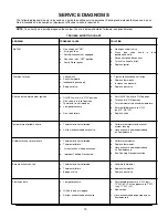

SERVICE
Servicing should only be performed by qualified &
licensed service companies.
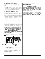
GAS VALVE
REGULATOR ADJUSTMENT
Recommended gas pressure at manifold
(4.0" W.C. Natural gas 10.0" W.C. Propane gas)
Adjustment of the gas valve pressure regulator is not
normally necessary since it has been preset at the fac-
tory. During installation, the gas pressure should be
checked at each gas valve with all burners operating.
Adjustment may be accomplished as follows:
This adjustment must be performed by a qualified tech-
nician.
1. Locate the gas valves.
2. With the griddle turned off, connect the monometer
to the pressure tap on the gas valve to be tested.
3. Turn the unit on and take the reading after all the
burners have ignited.
4. Make the necessary adjustments by removing the
screw cap on the pressure regulator cover exposing
the adjustment screw (clockwise will increase the
pressure, counterclockwise will decrease the pres-
sure).
Always check the screw cap on the pressure tap for
leaks after it has been removed and replaced.
GAS VALVE
REMOVAL AND REPLACEMENT
Disconnect the griddle from the gas supply.
1.
Lower the control panel. Remove the control panel
surround and upper heat shield.
2.
Remove the three wires connected to the gas
valve.
3.
Disconnect the pilot and burner feed from the front
of the gas valve.
4.
Access the pipe union at the rear of the gas valve
either from the front of the griddle or remove the
back of the cabinet and loosen the union.
5.
Remove two nuts on the rear of the gas manifold
and pull the gas manifold forward.
6.
Remove the gas valve and transfer the pipe and fit-
tings to the new gas valve. Transfer the pressure
tap to the new gas valve.
7.
Replace the gas valve by reversing the above
steps.
Always check for leaks at all joints and connections
using a soap solution mixed with water.
DO NOT USE AN OPEN FLAME TO CHECK FOR
GAS LEAKS.
Double check the wire connections to the gas valve;
improper connection could damage the gas valve.
ON/OFF SWITCH
REMOVAL AND REPLACEMENT
1.
Lower the control panel by removing the screws.
2.
Disconnect the wires on the switch and remove
switch.
3.
Snap the new switch into place and reconnect all
wires.
4.
Return the control panel to its normal position.
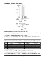
THERMOSTAT
REMOVAL AND REPLACEMENT
1.
Lower the control panel by removing the mount-
ing screws.
2.
Locate the bulb end of the thermostat and, using
a wrench, loosen the front and rear bolts holding
the thermostat bulb and shield in place.
3.
Slide the thermostat bulb assembly towards you
and remove it from under the griddle plate.
4.
Remove the knob and the screws from the ther-
mostat dial plate on the control panel.
5.
Remove the body of the thermostat.
6.
Install the new thermostat in the control panel,
replace the dial plate.
7.
Slide the thermostat bulb assembly into the
channel until it reaches the stop.
8.
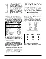
Make sure that the thermostat capillary and bulb
are completely protected by the shield, except for
1” at the tip of the thermostat bulb. (See Note 1).
9.
Make sure that the thermostat shield extends to
the front edge of the plate, and that the capillary
goes through the formed end of the shield. (See
Note 2).
10.
Make sure that the bolts which hold the thermo-
stat bulb and shield in place do not touch the
thermostat bulb. (See Note 3).
Tighten bolts 1/4 turn past finger tight bulb to be
snug against the bottom of the plate.
DO NOT OVERTIGHTEN THE BOLTS ON THE
THERMOSTAT SHIELD OR THEY
WILL
CRUSH THE THERMOSTAT BULB.
11.
Close the control panel and replace the panel
mounting screws.
NOTE:
IF REPLACING PUSH-ON TERMINAL
STYLE. Before installing thermostat into control
panel, you must unscrew the two brass terminal
screws and install the new ring terminal wire con-
nectors. Prior to connecting these wires, the
existing push-on terminal must be cut off and ring
terminals installed on them. Make sure that the
terminals are secured down.
12.
Calibrate the thermostat using an accurate grid-
dle thermometer. Locate the thermometer over
the thermostat bulb (shown by the "
Λ
" on the
front of the griddle plate) about half way toward
the back of the plate. Calibrate to the cooking
temperature you will be setting on the thermo-
stat.
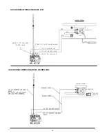
See Page 11 for
Proper Placement of the Thermostat Bulb
11
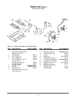
Summary of Contents for SERIES 2000
Page 17: ......