33
SySTEM DESCrIPTION
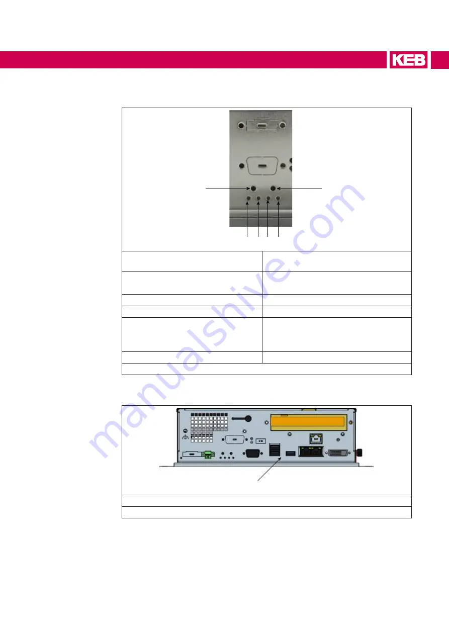
The buttons / LEDs area accommodates the following buttons / LEDs:
1
2 3 4 5
6
1 Reset
Act as hardware system reset without any
interaction with the operating system.
2 Over Temperature / Battery fault LED Red ON: Over temperature
Red Blink: Battery is fault
3 Watchdog LED
Reserved for future use.
4 HD LED
Amber: Access to hard disk
5 On / Off / Standby
Green ON: device is powered
Amber ON: device is shutdown
OFF: device is not powered
6 Watchdog Reset
Reserved for future use.
Figure 22: Buttons / LEDs area detail
2.6.4 Connectors area
1
1 Connectors area
Figure 23: Connectors area
Summary of Contents for C6 E22 BM-RVL
Page 1: ...EMBEDDED IPCS INSTRUCTIONS FOR USE E22 BOX PANEL Original Manual Document 20146638 EN 01 ...
Page 2: ......
Page 11: ...11 List of Figures Figure 89 External connectors 108 Figure 90 Buttons position detail 108 ...
Page 48: ...48 Installationand connection ...
Page 96: ...96 Drawings 7 1 4 C6 E22 PANEL SL S1 12 1 W Figure 75 12 1 Wide dimensions ...
Page 110: ...110 Certificatesandapprovals 8 Certificates and approvals 8 1 EU Declaration of conformity ...
Page 111: ...111 Certificatesandapprovals ...
Page 114: ......


