51
INSTALLATION AND CONNECTION
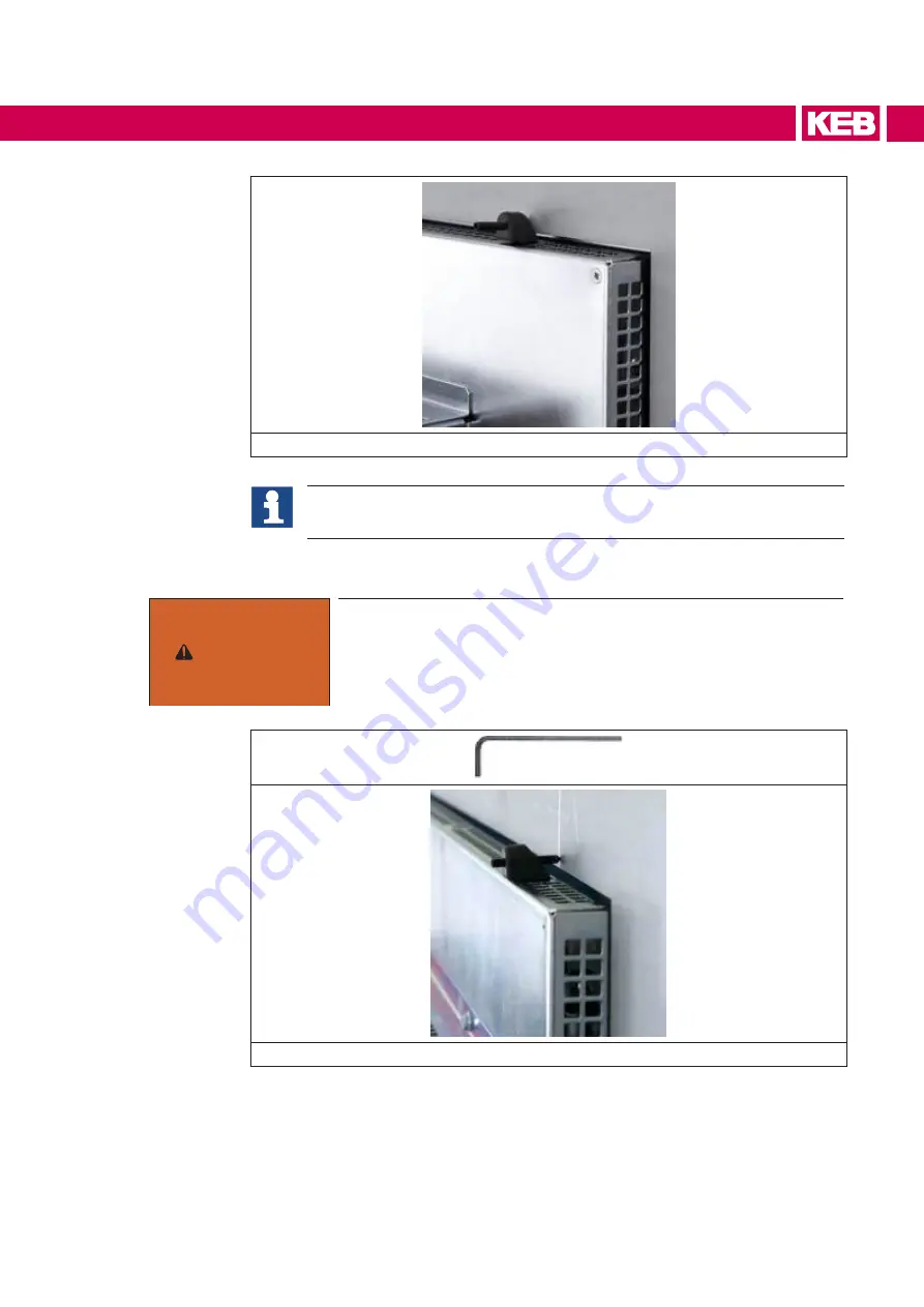
Figure 44: Installation
Mounting the clamps requires a space at least 20 mm on the outer perimeter
of the frame display.
• Tighten the mounting clamps with the hex key provided with (14 x 91 x 1.5 mm).
WArNING
The max. permissible torque for the mounting clamps is 0.2 Nm.
That means: tighten the mounting clamps only until the front gas-
ket is fully compressed. Do not tighten the mounting clamps more.
If the maximum permissible torque limit is exceeded, C6 E22 me-
chanical housing may be permanently damaged.
Figure 45: Installation
• Repeat the previous steps for all mounting clamps.
Summary of Contents for C6 E22 BM-RVL
Page 1: ...EMBEDDED IPCS INSTRUCTIONS FOR USE E22 BOX PANEL Original Manual Document 20146638 EN 01 ...
Page 2: ......
Page 11: ...11 List of Figures Figure 89 External connectors 108 Figure 90 Buttons position detail 108 ...
Page 48: ...48 Installationand connection ...
Page 96: ...96 Drawings 7 1 4 C6 E22 PANEL SL S1 12 1 W Figure 75 12 1 Wide dimensions ...
Page 110: ...110 Certificatesandapprovals 8 Certificates and approvals 8 1 EU Declaration of conformity ...
Page 111: ...111 Certificatesandapprovals ...
Page 114: ......


