54
INSTALLATION AND CONNECTION
3.9.4 Power supply connection
The device may be connected to a 24 VDC (18V÷32V) power supply which satisfies
the requirements of safe extra low voltage (SELV) in accordance with IEC/EN/DIN EN/
UL60950-1.
• Remove the two poles plug connector from the system.
• Connect the positive and the negative poles (also refer to the label on the back of
the system) to their respective terminals of the two pole plug connector. Use wires
with a cross-section of 1.5 mm2 (AWG16). Always check that the voltage drop along
the supply wiring is not excessive and the input voltage remains above the minimum
required (18V) in the worst load condition.
• Connect the ground cables (PE) to the earthing points.
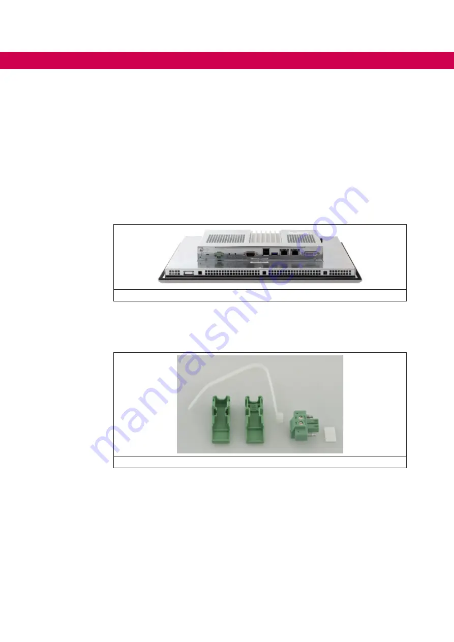
Figure 49:
C6 E22 BOX/PANEL detail
3.9.5 Power connector assembly
The system is equipped with a connector cup to be installed on the two poles power
connector. To properly assemble the connector, please follow these instructions:
Figure 50: Power connector assemply
Summary of Contents for C6 E22 BM-RVL
Page 1: ...EMBEDDED IPCS INSTRUCTIONS FOR USE E22 BOX PANEL Original Manual Document 20146638 EN 01 ...
Page 2: ......
Page 11: ...11 List of Figures Figure 89 External connectors 108 Figure 90 Buttons position detail 108 ...
Page 48: ...48 Installationand connection ...
Page 96: ...96 Drawings 7 1 4 C6 E22 PANEL SL S1 12 1 W Figure 75 12 1 Wide dimensions ...
Page 110: ...110 Certificatesandapprovals 8 Certificates and approvals 8 1 EU Declaration of conformity ...
Page 111: ...111 Certificatesandapprovals ...
Page 114: ......


