background image

GB - 11

3.

Installation

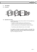
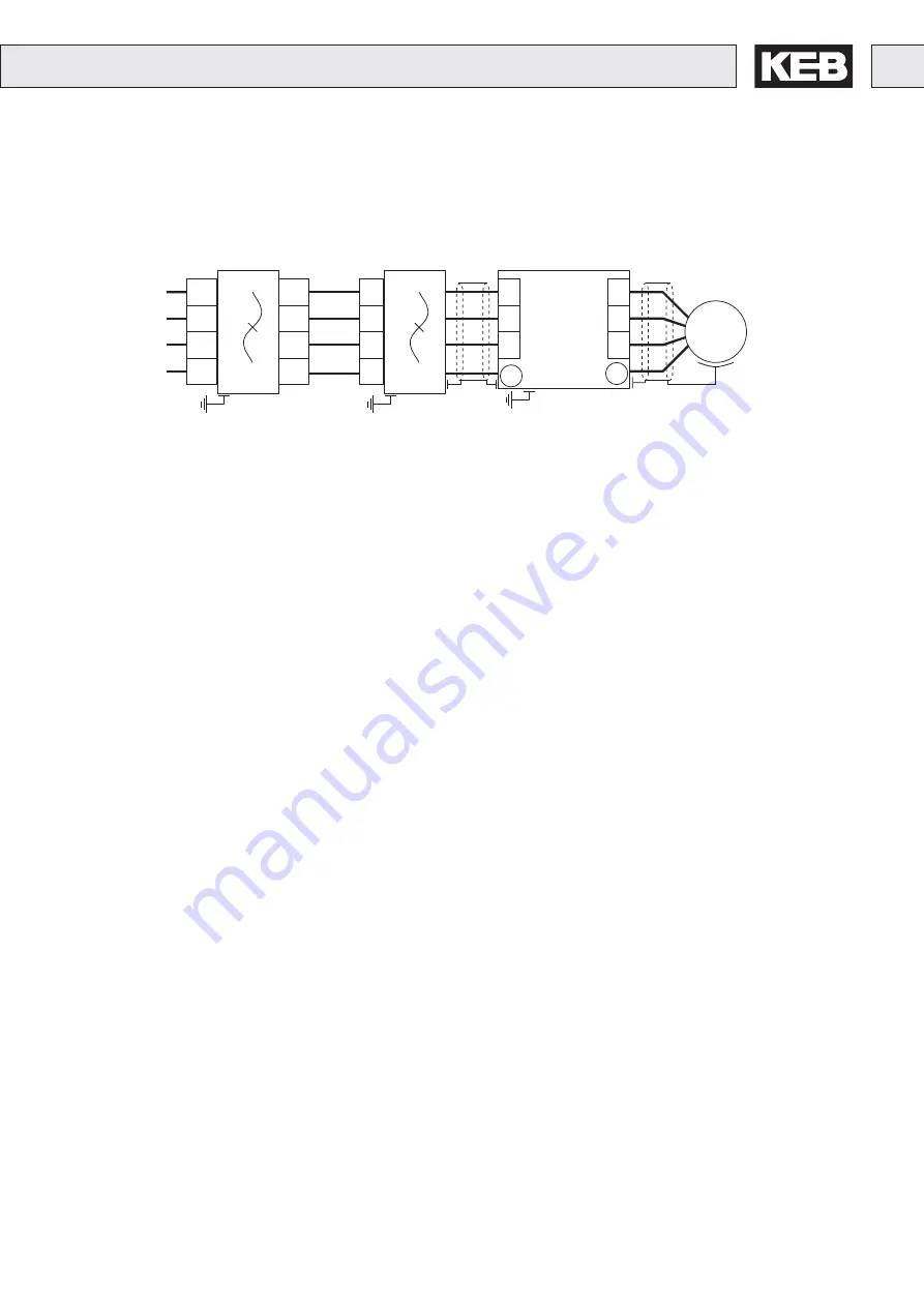
The KEB harmonic filter is to be used only as built-in unit. During installation pay
attention to the following:

- The distance to adjacent modules may not fall below 150 mm.

- A distance of 150 mm must be observed above and below the filter.

- Sufficient countermeasures must be taken against impurities of any kind.

- The permissible ambient temperatures may not be exceeded.

The installation of the filter can be made in standing or lying position. The
arrangement of the capacitors is below or beside the choke. In order to avoid
damage or destruction of the capacitors by overheat of the choke the capacitors
may not be arranged above the choke!

PE

L1
L2

KEB

COMBIVERT

U
V

W

PE

M

3~

L3

PE

L1.1
L2.1
L3.1

PE

L1
L2
L3

PE

L1
L2
L3

KEB

  COMBILINE

     HF-Filter

KEB

  Harmonic Filter

PE

L1.2
L2.2
L3.2

3.1

Connection

3.2

Installation Instructions

Summary of Contents for COMBILINE

Page 1: ...11 2005 BETRIEBSANLEITUNG KEB COMBILINE Harmonic Filter 00 U0 HE0 K310 ...

Page 2: ...2 ...

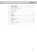
Page 3: ...nical Data of the 400V Class 7 2 2 Ambient Conditions 7 2 3 Input Rated Current 7 2 4 Dimensions 8 2 5 Description 9 3 Installation 11 3 1 Connection 11 3 2 Installation Instructions 11 4 Oscillograms 12 5 Annex 14 5 1 Fourier Analysis Spectrum 14 5 2 Formula 14 ...

Page 4: ...GB 4 ...

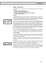
Page 5: ...DE 0100 VDE 0160 EN 50178 VDE 0113 EN 60204 as well as the appropriate regulations for your area Harmonic filters must be designed that they fulfill their function when the installation is correct and with specified application in error free operation and cause no danger for persons This applies also to the co operation with the entire system Use as directed The harmonic filter must not be started...

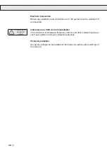
Page 6: ... Protect against accidental contact Instructions for EMC conform installation The connection line between frequency inverter and filter module must be as short as possible and close to reference potential Personal protection Dangerous voltage can be available at the mains connections after switching off the network ...

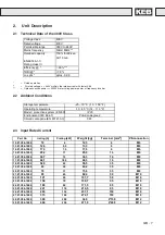
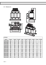
Page 7: ... 605 IP20 Environment IEC 664 1 Pollution degree 2 Climatic categorie EN 60721 3 3 3K3 Part No Irating A Prating kW Weight kg Terminal mm2 PE connection 12 Z1 C04 1000 10 4 12 3 4 M6 13 Z1 C04 1000 12 6 5 5 13 3 4 M6 14 Z1 C04 1000 17 3 7 5 17 6 4 M6 15 Z1 C04 1000 25 2 11 25 3 16 M6 16 Z1 C04 1000 34 7 15 36 3 16 M8 17 Z1 C04 1000 44 1 18 5 46 3 16 M8 18 Z1 C04 1000 52 5 22 55 5 35 M8 19 Z1 C04 1...

Page 8: ...16 18 Z1 C04 1000 352 184 256 324 328 224 144 10 16 19 Z1 C04 1000 352 192 268 325 328 224 152 10 16 20 Z1 C04 1000 388 184 240 337 364 248 144 10 16 21 Z1 C04 1000 412 192 311 385 388 264 152 10 16 22 Z1 C04 1000 412 214 378 404 388 264 175 10 16 23 Z1 C04 1000 480 212 337 408 450 316 163 12 20 24 Z1 C04 1000 552 242 481 472 516 356 182 14 5 24 25 Z1 C04 1000 552 272 511 468 516 356 212 14 5 24 2...

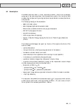
Page 9: ...onic filter optimal filter effect compact structure small space requirements for installation installation solution ready to connect clear reduction of the capacitive current during no load operation no tendency to oscillation during load change significant smaller voltage drop compared to mains choke Increase of the inverter lifetime by means of the trapezoidal output voltage and the square wave ...

Page 10: ... of companies Disturbances or damages at these units can have effects to the power supply of the company and they can cause losses of production In practice many reactive power compensation equipments without choke are still used Various problems can occur in this connection direct resonance resonance danger switching transient interference of ripple control transmission For the case that resonanc...

Page 11: ...ny kind The permissible ambient temperatures may not be exceeded The installation of the filter can be made in standing or lying position The arrangement of the capacitors is below or beside the choke In order to avoid damage or destruction of the capacitors by overheat of the choke the capacitors may not be arranged above the choke PE L1 L2 KEB COMBIVERT U V W PE M 3 L3 PE L1 1 L2 1 L3 1 PE L1 L2...

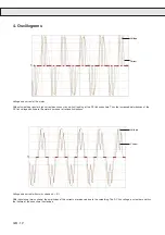
Page 12: ... disturbances of the DC link voltage continue to the motor by manner of torque fluctuations Voltage and current with mains choke uk 4 With inductance mains choke the amplitudes of the currents are reduced due to the smoothing The DC link voltage is smoother and thus the lifetime of the capacitors is extended 4 Oscillograms Voltage Current Voltage Current ...

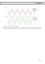
Page 13: ...e line side sinusoidal current the amplitudes of the currents are reduced again compared to the choke The output variables are nearly rectangular and they cause so a very smooth voltage in the DC link and an increased lifetime of the capacitors Voltage Current Voltage Current Input Output ...

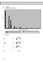
Page 14: ...der Oberschwingung Strom I in von IH01 Spektrum des Eingangsstromes eines KEB OSF 8 THDI Spektrum des Eingangsstromes eines KEB FU ohne Drossel Spektrum des Eingangsstromes eines KEB FU mit Drossel 5 Annex 5 1 Fourier Analysis Spectrum 5 2 Formula 2 40 2 1 n N I I THD 2 40 14 1 n N I I n PWHD equ i equ I U S 3 equ sc sce S S R THD PWHD Sequ Rsce ...

Page 15: ......

Page 16: ...rançaise KEB Z I de la Croix St Nicolas 14 rue Gustave Eiffel F 94510 LA QUEUE EN BRIE fon 33 1 49620101 fax 33 1 45767495 net www keb fr mail info keb fr KEB UK Ltd 6 Chieftain Buisiness Park Morris Close Park Farm Wellingborough GB Northants NN8 6 XF fon 44 1933 402220 fax 44 1933 400724 net www keb uk co uk mail info keb uk co uk KEB Italia S r l Via Newton 2 I 20019 Settimo Milanese Milano fon...

Reviews: