60
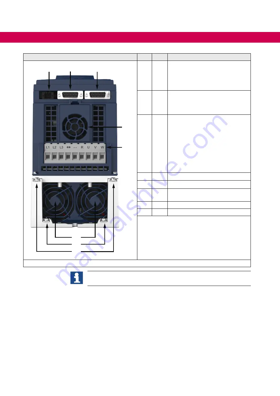
OVerVIeW OF THe cOMbIVerT F6
Housing 2
No. Name
Description
8
6
7
9
4
5
5a
10
4
X1A
Power circuit terminals for:
• Mains input
• Braking resistor
• DC supply
• Motor connection
5
PE
Protective earth;
at connection to protective earth
each terminal may be assigned only
once.
5a
---
Fixing points for the optional shielding
plates. The shielding e.g. from the
motor cable is laid on the mounting
plate in the control cabinet or on the
shielding plates (optionally available).
Power unit:
• Built-in version
00F6V80-2001
• Push-through version
00F6V80-2002)
6
X3A Encoder interface channel A
7
X3B Encoder interface channel B
8
X1C Motor temperature monitoring, brake
control
9
---
Interior fan
10
---
Heat sink fan
Figure 15:
F6 housing 2 front view
Terminal R can alternatively be labeled with PB.
Summary of Contents for COMBIVERT 10F6 Series
Page 2: ......
Page 82: ...82 NOTES...


