ANTRIEBSTECHNIK
GB 13
GB
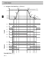
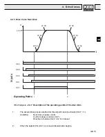
WHAT HAPPENS WHEN?
Description of the Operating Points of the Main Drive
1:
Presetting of the setpoint for the drive speed and the selection of the direction
of travel. The inverter checks whether input X3.1 (contactor control) is set. If
yes the output X3.20 (main contactor control) is set. If X3.1 is not set, the
display “E.Co“ is seen in LF.98 and output X3.20 is not set.
2:
If X3.20 is set, then X3.1 must be reset.
3:
X2.1 (control release) is set with the precontrol contact of the main contact.
After this is done the inverter provides the motor with current, when the main
contacts are connected (powerless switching).
When the safety Circuit is interrupted input X2.1 must be reset immediately.
(see „Control instructions“ page GB 60)
4:
When the motor can receive a current (“hardware test”), the output X3.15 (brake)
is set. If there is not enough current flowing, you will see the display “E.nC” in
LF.98 and X3.15.
5:
After X3.15 is set, the brake release time (LF.70) runs out; then the motor starts
to turn.
6:
When exceeding the monitoring of the crawl speed (LF.63) the output X3.18 is
reset.
7:
When exceeding the monitoring of the deceleration check (LF.62) the output
X3.17 is reset.
8:
When the setpoint is removed for the rated speed (X3.4) deceleration starts.
9:
When exceeding the monitoring of the deceleration check (LF.62) the output
X3.17 is set.
10:
When exceeding the monitoring of the crawl speed (LF.63) the output X3.18 is
set.
11:
When the limit switch is reached, the set value for the positioning speed is set
at 0 and thus the drive keeps the cabin floating until the brake is engaged,.
12:
When the operating point of the brake (LF.60) is exceeded, the output X3.15 is
reset.
13:
When X3.15 is reset, the modulation is switched off after two times of LF.70
(brake release time). 0,3 s later output X3.20 is reset.
4. Drive
Curves
Summary of Contents for COMBIVERT F4-F
Page 65: ...ANTRIEBSTECHNIK...


