11
6
3
11
KEB COMBIVERT F5
Name: Basis
28.01.03
6
Section
Page
Date
©
KEB Antriebstechnik, 2002
All rights reserved
Chapter
Functional Description
Digital In- and Outputs
do.2
do.4
do.6
do.0
do.1
do.3
do.5
do.7
do.8
1
2
...
128
do.16
do.9 do.17
do.10
do.18
do.11
do.19
do.12
do.20
do.13
do.21
1
2
...
128
8
8
8
8
8
8
1
2
...
128
1
2
...
128
1
2
...
128
1
2
...
128
do.14
do.22
8
1
2
...
128
do.15
do.23
8
1
2
...
128
do.25
1
2
...
128
do.33
do.26do.34
do.27
do.35
do.28
do.36
do.29
do.37
do.30
do.38
1
2
...
128
8
8
8
8
8
8
1
2
...
128
1
2
...
128
1
2
...
128
1
2
...
128
do.31
do.39
8
1
2
...
128
do.32
do.40
8
1
2
...
128
do.42
1
2
4
8
16
32
64
128
&
>1
2
0
=1
8
8
&
>1
8
8
&
>1
8
8
&
>1
8
8
&
>1
8
8
&
>1
8
8
do.24
8
8
8
8
&
>1
&
>1
2
1
=2
2
2
=4
2
3
=8
2
4
=16
2
5
=32
2
6
=64
2
7
=128
&
>1
2
0
=1
8
8
&
>1
8
8
&
>1
8
8
&
>1
8
8
&
>1
8
8
&
>1
8
8
do.41
8
8
8
8
&
>1
&
>1
2
1
=2
2
2
=4
2
3
=8
2
4
=16
2
5
=32
2
6
=64
2
7
=128
8
8
0
1
2
3
4
5
6
7
8
9
10
11
12
13
14
15
16
17
18
19
20
21
22
23
z
-1
z
-1
do.43
do.44
1
1
1
1
1
1
1
1
1
1
1
1
1
1
1
1
1
1
1
1
1
1
1
1
1
1
1
1
1
1
1
1
1
1
1
1
1
1
1
1
1
1
1
1
1
1
1
1
1
1
1
1
1
1
1
1
8
do.51
0
1
2
3
O1=O1
O1=O2
O1=R1
O1=R2
0
4
8
12
O2=O1
O2=O2
O2=R1
O2=R2
0
16
32
48
R1=O1
R1=O2
R1=R1
R1=R2
0
64
128
192
R2=O1
R2=O2
R2=R1
R2=R2
Bit 0-1
Bit 2-3
Bit 4-5
Bit 6-7
4
4
4
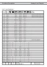
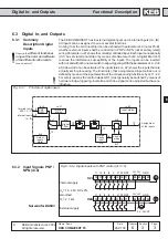
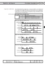
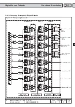
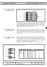
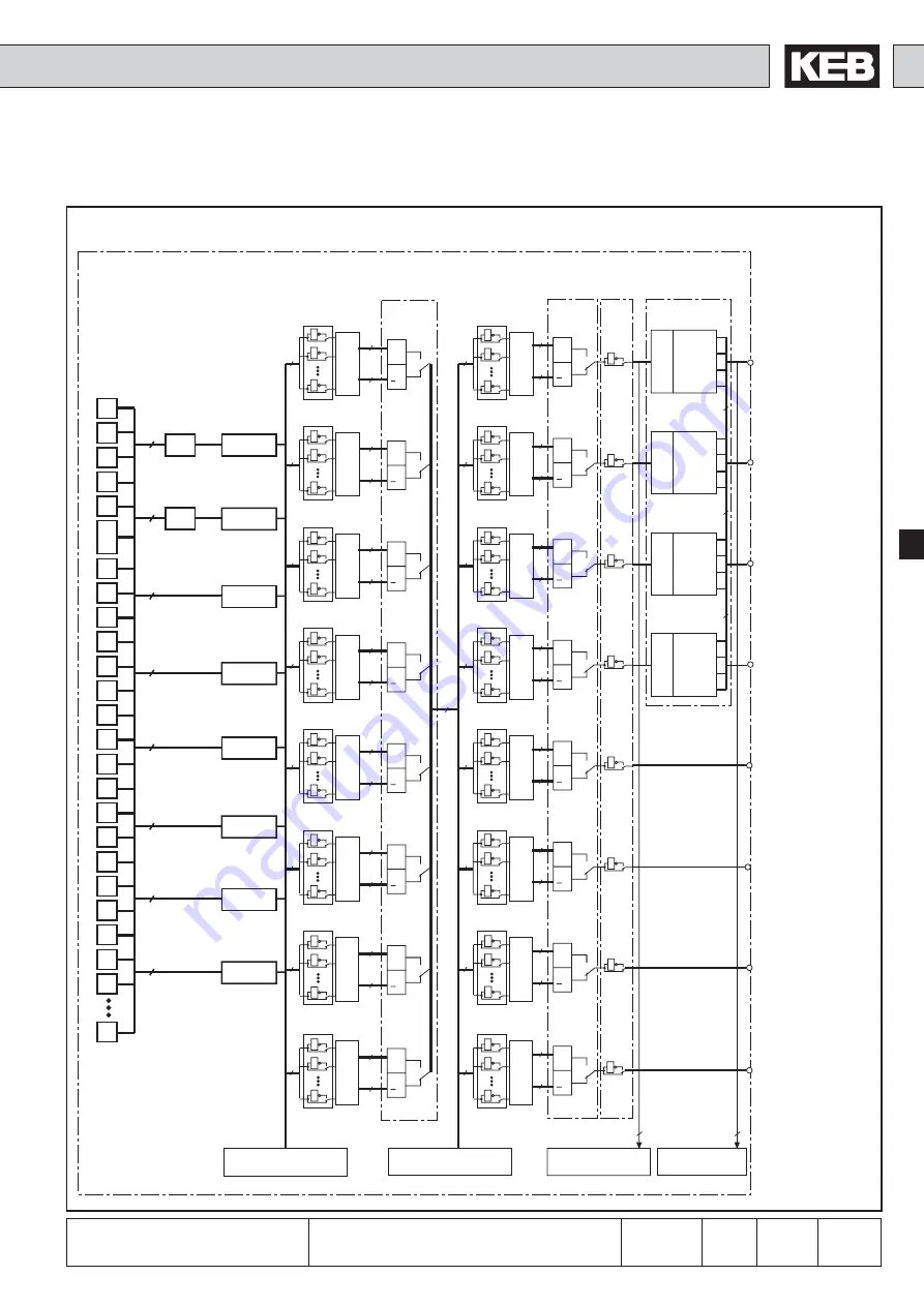
6.3.12 Summary Description - Digital Outputs
Fig. 6.3.12
Principle of digital outputs
Internal output OD
Internal output OC
Internal output OB
Internal output OA
Relay output (R2)
X2A.27...29
Transistor output
(O2)
X2A.19
Transistor output
(O1)
X2A.18
Relay output (R1)
X2A.24...26
Flag 0...7
Outputs
ru.23 Output
condition status
ru.24 Status
of output flags
ru.25 Output
terminal Status
Condition 0...7
1 von75
75
1 von 75
1 von 75
1 von 75
1 von 75
1 von 75
1 von 75
1 von 75
75
75
75
75
75
75
75
75
ru.80 digital
output state


