6
3
KEB COMBIVERT F5
14
Name: Basis
28.01.03
Chapter
Section
Page
Date
©
KEB Antriebstechnik, 2002
All rights reserved
Functional Description
Digital In- and Outputs
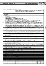
33
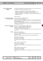
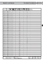
AN3 on output of characteristic amplifier > level; without sign evaluation
34
AN1 on output of characteristic amplifier > level; with sign evaluation
35
AN2 on output of characteristic amplifier > level; with sign evaluation
36
AN3 on output of characteristic amplifier > level; with sign evaluation
37
Timer 1 > level
38
Timer 2 > level
39
Angle difference > level (only F5-M/S)
40
Hardware current limit active
41
Modulation on-signal
42
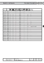
Output of analog signal ANOUT3 as PWM-signal. The period is adjusted with An.46.
43
Output of analog signal ANOUT4 as PWM-signal. The period is adjusted with An.52.
44
Inverter state (ru.0) = Level
45
Power module temperatur (ru.38) > Level
46
Motor temperatur (ru.46) > Level
47
Ramp output value (ru.2) > Level
48
Apparent current (ru.15) > Level
49
Clockwise rotation (not at noP, LS, abnormal stopping, error)
50
Counter clockwise (not at noP, LS, abnormal stopping, error)
51
Warning E.OL2
52
Current control at the limit (only F5-M/S)
53
Speed control at the limit
54
Target window reached (Posi module at F5-M/S)
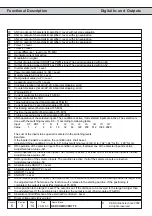
55
Current position > Level (Posi module at F5-M/S)
56
Positioning active (Posi module at F5-M/S)
57
Position inaccessible (Posi module at F5-M/S)
58
Profile processing active (Posi module at F5-M/S)
59
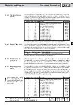
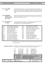
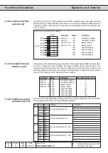
AND-operation of the selected inputs. The condition is active, if all selected inputs are active. The selection is
done with the switching levels (LE.0...7) according to following table:
Input
ST
RST
F
R
I1
I2
I3
I4
IA
IB
IC
ID
Value
1
2
4
8
16
32
64
128
256
512
1024 2048
The sum of the inputs to be queried is entered in the switching levels.
Example:
If the inputs I3 and I4 are active, the condition do.4 shall be set.
Adjust switching condition 4 (do.4) to „59“. Adjust switching level 4 (LE.4) to „192“ („64“ for I3 + „128“ for I4).
60
OR-operation of the selected inputs. The condition is active, if at least one of the selected inputs is active.
Adjustment as at value „59“.
61
NAND-operation of the selected inputs. The condition is active, if at least one of the selected inputs is inactive.
Adjustment as at value „59“.
62
NOR-operation of the selected inputs. The condition is active, if all of the selected inputs are inactive.
Adjustment as at value „59
63
Absolute value ANOUT1 > Level
64
Absolute value ANOUT2 > Level
65
ANOUT1 > Level
66
ANOUT2 > Level
67
Active relative position > Level. The output is set, if the distance covered after the starting position is larger than
the adjusted level. That means, the function works relative to the starting position. If the positioning is
completed, the output is reset (Posi module at F5-M/S).
68
Active position to the target > Level. The output is set, if the distance to be covered to the target is larger than
the adjusted level. If the positioning is completed, the output is reset (Posi module at F5-M/S).
69
Absolute control difference of the external PI controller > Level
70
Driver voltage activ (driver relay)

