13
6
7
13
KEB COMBIVERT F5
Name: Basis
04.05.04
6
Abschnitt
Seite
Datum
©
KEB Antriebstechnik, 2002
All rights reserved
Kapitel
Functional Description
Protective Functions
6.7.7
Quick Stop
(Pn.58...60)
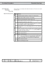
The function Quick Stop is triggered through malfunctions (abnormal stopping) or by
the control word (sy.50 Bit 8). It is defined by the following parameters.
The Quick Stop mode determines the basic operating mode of the function.
Pn.58
Description
Bit 0
Control mode
0
Control via ramp generator (default)
1
Control via differential controller
Bit 1
Actual value for differential controller
0
Apparent current (default)
2
Active current
Bit 2
Behavious at standstill after activation by control word (sy.50)
0
Modulation off
4
Holding torque
The Fast Stop level determines the setpoint value for the differential control. The
adjustable value of 10...200% refers to a rated inverter current (In.1).
Depending on the adjustment of the control mode in Pn.58 the ramp time or the time
constant of the differential controller is adjusted here within the range of 0...300.00 s
(default 2.00 s). The ramp time refers to 100 Hz / 1000 rpm (depending on ud.2).
Adjustment of the torque limit during fast stop in the range of 0...10000 Nm. Pn.61 is
limited to dr.15 (max. torque FI) and dr.33 (three-phase motor) (dr.15 > dr.33 > cS.19).
Setting of the max. torque at field weakening speed (dr.18) during quick stop in the
range 0...10000,00 Nm (also see chap. 6.6.4).
Regulation by ramp generator
Quick stop with time delay stop (LD(U)-Stop) onto the minimum output value (op.36 /
op.37). At abnormal stopping with holding torque the modulation remains switched
on, otherwise it is switched off (also at quick stop by control word sy.50 Bit 8).
Regulation by differential controller
Quick stop with time delay stop (LD(U)-Stop) onto the minimum output value (op.36 /
op.37) with variable step size (see below). At abnormal stopping with holding torque
the modulation remains switched on, otherwise it is switched off.
The differential controller changes the adjusted step size (from pn.60), if the actual
value is larger than the setpoint value:
100 Hz
Adjusted step size
= ————–
ramp time
Setpoint value - Actual value
Step size = adjusted step size * (1 + —————————————— )
Inverter rated current
Quick Stop / Level (Pn.59)
(F5-G)
Quick Stop / Ramp time
(Pn.60)
Quick Stop / Mode (Pn.58)
Function description F5-G
Quick Stop / Torque limit
(Pn.61) (F5-M/S)
Quick stop / max. torque at
corner speed (Pn.67) (F5-M/S)

