Connection of the control | 4
ma_dr_f6-cu-p-inst-20182705_en
23
In order to calculate the input current, the currents of the power unit, control and
other loads must be added together. The actual current required can be used for
the consumers. The maximum current must not be exceeded.
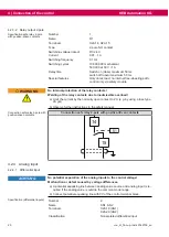
4.2.6.1.2 External supply
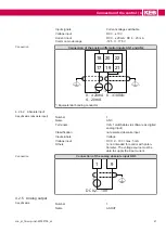
Specification external supply
Name
P24Vin, 0V
Terminals
X2A.28 (P24Vin)
X2A.27 (0V)
Voltage
DC 24 V (+20 % / -17 %)
Current consumption
Calculated value up to max. 4.8 A
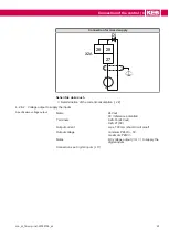
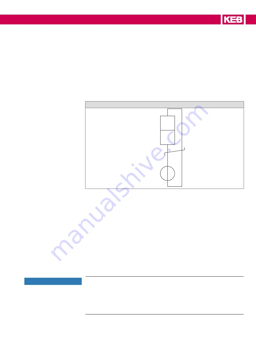
Connection of the external supply
27
28
+
-
X2A
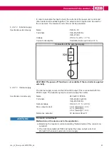
ACHTUNG! The power-off function is not available if the controller is supplied
externally.
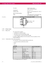
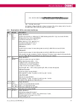
4.2.6.1.3 Internal supply
The internal supply occurs via the 24VoutCtrl output. This is connected with the
P24Vin input. The output may only be used to supply the control.
Specification internal supply
Name
24VoutCtrl; P24Vin
Terminals
X2A.26 (24VoutCtrl)
X2A.28 (P24Vin)
Output voltage
DC 24 V (-17 % / +20 %)
Max. output current
1.5 A (housing 2 / 3 / 4)
2.1 A (housing 6)
2.5 A (housing 7 / 8 / 9)
Reference potential
0V (terminal X2A.27)
ACHTUNG
Too much current load!
Malfunctions at the device and in the application.
a) Determine the maximum current according "Determination of the current con-
sumption".
b) If current consumption at P24Vin is higher than max. output current at
24VoutCtrl, then select external or mixed supply.


