GB - 25
Control
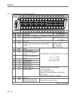
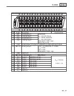
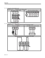
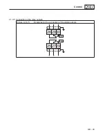
4.1.4 Control terminal strip X2A
The control terminal strip is designed as a double, plug-in terminal strip with spring cage con-
nection. It contains 32 pole. The following instructions must be observed at connection:
Attention
Prevent EMC malfunctions
•
Use shielded / drilled cables
•
Lay shield on one side of the inverter onto earth potential
•
Lay control and power cable separately (about 10...20 cm apart); Lay
crossings in a right angle (in case it cannot be prevented)
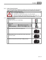
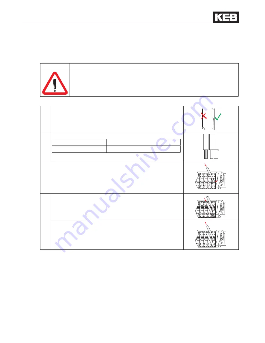
4.1.4.1 Assembly of the wires
Required tools:
Screw driver SD 0,4 x 2.5 (DIN 5264)
1. Strip cable
Cable
permissible cross-section
rigidly and flexibly
0.08…1
mm2 (AWG22…18)
7mm
2. Plug screw driver mid into the square slot
3. Plug cable into the round slot, that no wires can be seen
from the outside.
4.
Remove screw driver and check if cables are fixed.
Summary of Contents for COMBIVERT G6 series
Page 1: ...C O M B I V E R T Mat No Rev 00G6NEM DC00 1G GB Installation Manual Housing C Power 5 5 11kW...
Page 2: ......
Page 4: ...GB 4 Table of Contents...
Page 37: ...GB 37 Parameter Description...
Page 41: ...GB 41 Notes...


