GB - 16
R4
-IN
-OUT +OUT
+IN
L1_2
PE
L2_2
L3_2
PE
L1 L2 L3
L1
L2
L3
FU
+U
ZK
-U
ZK
L1
L2
L3
U V W
HF-
Filter
(R4)
PE
M
3~
3
L1
L2
L3
FU
Filter
L1
L2
L3
L3'
L3'
L2'
L2'
L1'
L1'
L1
L2
L3
PE
L1
L2
L3
HF-
Filter
(R4)
3
L1
L2
L3
L1
L2
L3
L3'
L3'
L2'
L2'
L1'
L1'
R4
-IN
-OUT +OUT
+IN
L1_2
L2_2
L3_2
PE
L1 L2 L3
R4
-IN
-OUT +OUT
+IN
L1_2
L2_2
L3_2
PE
L1 L2 L3
FU
+U
ZK
-U
ZK
L1
L2
L3
U V W
PE
M
3~
I
nom. inverter
> I
nom. feedback
4.2.2
Parallel Operation
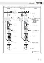
If the expected feedback power is higher than the rated power of a R4-S-rege-
nerative unit, the feedback power can be increased by cascading of two or more
R4-S-regenerative units. In this constellation the feedback power is increased
by the value of the rated power of the additional R4-S-regenerative units.
During parallel operation an own commutating choke must be connected to every
R4-S-regenerative unit. The fuses must be set in front of the terminal connection
of the DC-bus for protection against the short-circuit current (see chapter 4.3
Connection of the control - parallel operation of several R4-S-regenerative units).
I
nom. inverter
<
∑
I
nom. feedback
Installation


