background image

GB - 21

e

l

p

i

c

n

i

r

p

n

o

i

t

a

l

l

a

t

s

n

I

)

y

l

b

m

e

s

s

a

b

u

s

l

a

u

d

i

v

i

d

n

i

f

o

t

n

e

m

e

g

n

a

r

r

a

t

c

a

p

m

o

c

r

o

f

(

U

F

7

1

e

z

i

S

7

1

e

z

i

S

>

U

F

d

n

e

g

e

L

1

2

3

4

5

6

7

8

e

s

u

f

n

i

a

M

n

o

i

t

c

e

t

o

r

p

n

i

a

M

-

p

p

u

s

-

e

c

n

e

r

e

f

r

e

t

n

i

-

o

i

d

a

R

r

e

t

li

f

d

e

s

s

e

r

U

F

.

u

4

R

r

e

t

li

F

=

a

3

U

F

r

e

t

li

F

=

b

3

4

R

r

e

t

li

F

=

c

3

e

k

o

h

c

g

n

i

t

a

t

u

m

m

o

C

t

i

n

u

k

c

a

b

d

e

e

F

-

S

-

4

R

e

s

u

f

s

u

b

-

C

D

r

e

t

r

e

v

n

i

y

c

n

e

u

q

e

r

F

r

o

t

o

M

g

n

i

t

n

u

o

m

d

e

z

i

n

a

v

l

a

G

e

t

a

l

p

M

3~

c

b

M

3~

a

R4

R4

FU

FU

PE

L1, L2, L3

3a, 3b, 3c

1

2

4

5

6

7

8

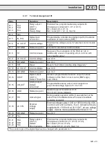
Installation

Summary of Contents for COMBIVERT R4-S

Page 1: ...00 R4 S10 K150 BETRIEBSANLEITUNG INSTRUCTION MANUAL COMBIVERT Version 1 5 04 03...

Page 2: ...Die in dieser Betriebsanleitung verwendeten Piktogramme haben folgende Bedeutung Remark Before you start with the installation of the R4 S regenerative unit please read this manual carefully and pay...

Page 3: ...2 2 Parallel Operation 16 4 2 3 R4 S Regenerative unit and Supply Unit 17 4 2 4 R4 S as Combination with Inverter 18 4 2 5 Hints for EMV Conform Wiring 19 4 3 Connection of the Control 22 4 3 1 Termi...

Page 4: ...User Definition ud Parameter 34 5 4 2 5 Free programmable Fr Parameter 35 5 4 2 6 Analog I O An Parameter 36 5 4 2 7 Digital Input di Parameter 37 5 4 2 8 Digital Output do Parameter 39 5 4 2 9 Level...

Page 5: ...2 3 4 6 32 Parameter Description ud 7 33 Fr Free programmable 33 Parameter Description Fr 0 1 33 An Analog I O 34 Parameter Description An 14 15 16 17 34 di Digital Input 35 Parameter Description di...

Page 6: ...and experience those with knowledge of the relevant standards and who are familiar with the field of power trasmission EN 50178 VDE 0100 VDE 0160 EN 60204 VDE 0113 as well as the approporiate regulati...

Page 7: ...VDE 0113 the power semiconductor of the unit must be disconnected because of the danger of destruction This is permissble in compliance with the standard since all inverters are given a high voltage...

Page 8: ...h overcurrent protective devices With IT mains it is insulation monitoring with a pulse code measuring method A protective separation can be used with all mains forms as long as the required power and...

Page 9: ...feedback in connection with nearly all standard frequency inverters of 200V 400 V Class These should be used when motors are connected to frequency inverters and because of the special conditions ope...

Page 10: ...supply Uout 18 V DC max Output current Iout 300 mA external voltage supply Uin 24 V DC 10 25 Limiting continous current ImR 1A max switching voltage UmR 30V DC Installation Operating temperature TB 1...

Page 11: ...start up of the R4 S regenerative unit is only allowed by qualified personnel Safe and trouble free operation is only possible with the following standards DIN VDE 0100 DIN VDE 0113 DIN VDE 0160 DIN...

Page 12: ...0 4 3 0 3 2 5 6 0 0 1 0 2 3 g k 5 8 a c 9 1 0 1 0 6 T 4 R 1 2 0 4 1 0 6 4 4 3 2 5 6 0 0 1 0 5 4 g k 6 1 a c 9 1 0 1 0 6 T 4 R 2 2 0 7 2 5 9 6 0 3 1 6 1 0 3 2 5 5 6 g k 9 2 a c t s e u q e r n o 9 1 0...

Page 13: ...1 g k 4 4 1 4 8 4 8 0 R R D 2 2 5 0 2 0 5 3 0 0 3 5 1 0 3 1 0 4 2 g k 5 3 5 F B H G C A 15 cm 15 cm 3 cm 4 1 2 Installation Instructions The R4 S regenerative unit is designed for a installation in a...
Page 14: ...r shielding earthing Terminal marking Installation Bridge when there is no monitoring Thermo contact Break contact Temperature detector PTC Operate resistor 1 65 4 kOhm Resetting resistor 0 75 1 65 kO...

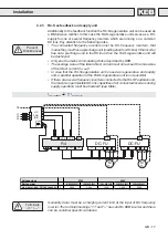
Page 15: ...e semiconductors but they don t have the function to protect conductor cross sections To avoid invalid high commutation notches a commutating choke Art No see 2 4Technical data must be connected on li...

Page 16: ...s higher than the rated power of a R4 S rege nerative unit the feedback power can be increased by cascading of two or more R4 S regenerative units In this constellation the feedback power is increased...

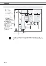
Page 17: ...ill be destroyed Only use the mains commutating choke described by KEB The average value of the taken direct current must not exceed the max value of the direct current IDC MAX In case that the R4 S r...

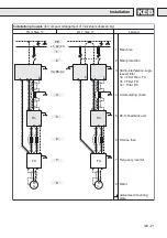
Page 18: ...regenerative unit can be combined with frequency inverters with DC bus connection see picture 1 In this case the frequency inverter must be con nected to the supply via a separate choke 4 UK see pictu...

Page 19: ...possible to 30cmfrom the interference source and in metal to metal contact with the mounting plate with a large contact surface Always equip inductive control elements contactors relays etc with suppr...

Page 20: ...S E P t n i o p r a t s n o m m o c a 9 E P t n i o p r a t S e g n a r l o r t n o c r o f 0 1 g n i h t r a e l a i t n e t o p i u q E 3 1 n o i t c e n n o c s n i a M a 3 1 n o i t c e n n o c s...

Page 21: ...a M n o i t c e t o r p n i a M p p u s e c n e r e f r e t n i o i d a R r e t l i f d e s s e r U F u 4 R r e t l i F a 3 U F r e t l i F b 3 4 R r e t l i F c 3 e k o h c g n i t a t u m m o C t i...

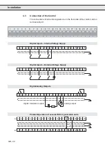
Page 22: ...4 5 6 7 8 9 10 11 12 13 14 15 16 17 18 19 20 21 22 23 RS 1 2 3 4 5 6 7 8 9 10 11 12 13 14 15 16 17 18 19 20 21 22 23 4 3 Connection of the Control The connections of all control signals are on the fro...

Page 23: ...t s r o f t u p t u o r o t s i s n a r t e l b a m m a r g o r p d e t a l o s I c i g o L P N P l o r t n o c t s o h o t S 4 R e h t f o n o i t a c i d n i A m 0 2 x a m 5 1 1 X T U O _ N A t u p...

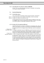
Page 24: ...nisation the actual mains frequency is set and the connection of the R4 S regenerative unit is correct If the release signal terminal ST is set the R4 S regenerative unit takes independently its funct...

Page 25: ...e t t i m s n a r T 9 B B D x T 5 8 4 S R B l a n g i s r e t t i m s n a r T FUNC SPEED START STOP ENTER F R 5 4 3 2 1 9 8 7 6 Operating the Unit 5 2 1 Operation with Interface Operator Local Operat...

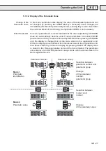
Page 26: ...nd indicates which part can be changed with UP DOWN With ENTER the flashing dot can be changed between parameter group and parameter number To change the parameter group the ENTER key must be pressed...

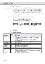
Page 27: ...ed ENTER parameters since they must be confirmed by ENTER When pressing UP DOWN only the display is changed but not the value stored in the regenerative unit When the display value is different from t...

Page 28: ...h t r o f s n o i t i d n o c g n i h c t i w S n o i t a m r o f n I n I r e t e m a r a p s i s o n g a i d d n a r e b m u n l a i r e s e p y t t u o b a n e n o i t a m r o f n I c t e r e b m u...

Page 29: ...P r e d n U C O E 4 x 6 1 t n e r r u c t u p t u o t n e r r u C r e v O d e t a r I H O E 8 t i n u k c a b d e e f e h t f o g n i t a e h r e v o t a e H r e v O H O d E 9 r u t a r e p m e t t a...

Page 30: ...a i v d e t e l e d e b n a c y r o m e m k a e p e h T t e s e R n O r e w o P g n i s s e r p y b d e t e l e d e b n a c 2 1 u r 4 1 u r s u t a t S l a n i m r e T t u p n I e n o f I n o i t a r...

Page 31: ...s l a r e v e s f I d e y a l p s i d s i e u l a v l a m i c e d g n i d n o p s e r r o c d e y a l p s i d s i e u l a v o N t i B e u l a V l a m i c e D t u p n I s l a n i m r e T 0 1 C L F B L...

Page 32: ...i t c n u F 6 1 n P H O d E r o r r E e m i T k a e r B l a n g i s l a n r e t x e e h t r e t f a d e y a l e d e b n a c e k o h c g n i t a t u m m o c e h t f o t a e h r e v o H O d E r o r r e...

Page 33: ...e v e l e h t s e g n a r r e v o e l p m a x E t n e m t s u j d A e g a t l o V y l p p u S e g a t l o V s u b C D e g a t l o V k c a b d e e F 5 0 1 7 2 S C U t e n V 0 0 4 U K Z U t e n x x V 0...

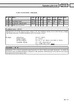
Page 34: ...o l l a t o n s e o d t i n u e h t f o M O R P E E y r o m e m r e t e m a r a p e h T n e t t i r w l l a t a h t r e t f A y r o m e m r e t e m a r a p e h t d n e t x e o t 0 o t t e s e b n a c...

Page 35: ...s g n i t t e s c i s a b d e r o t s e h t y p o c n a c u o y 2 t i n i n o i t c n u f h t i W s e u l a v t l u a f e d e h t h t i w n e t t i r w r e v o e r a s t n e m t s u j d a r e t e m a...

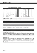
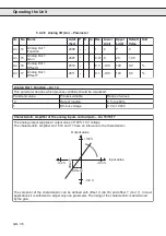
Page 36: ...1 e g a t l o v s u b C D V 0 0 0 1 o t V 0 7 1 6 1 5 1 n A s t u p t u o d n a s t u p n i g o l a n a e h t f o r e i f i l p m a c i t s i r e t c a r a h C e g a t l o v V 0 1 0 0 1 f o e u l a v...

Page 37: ...l e S e u l a v r e t e m a r a P l a n i m r e t t u p n i e h t f o c i g o L 0 P N P 1 N P N 0 i d r e t l i f e s i o n l a t i g i D s t u p n i l o r t n o c t a s n o i t c n u f l a m t s n i...

Page 38: ...t c n u F t u p n I d e t s u j d a s i 1 I t u p n i e l b a m m a r g o r p e h t f o n o i t c n u f e h t 3 i d h t i W e u l a V r e t e m a r a P n o i t c n u F t u p n I 0 n o i t c n u f o n...

Page 39: ...1 A 2 1 0 7 0 o d 9 1 c i g o l n o i t i d n o c 3 t u O 3 1 A 2 1 0 7 0 o d 5 2 n o i t c e n n o c n o i t i d n o c t u p t u O 9 1 A 2 1 0 7 0 0 o d c i g o L t u p t u O d e t r e v n i h c a e...

Page 40: ...i d e t s u j d a s i e u l a v l a m i c e d e v i t c e p s e r e h t t u p t u o g n i d n o p s e r r o c e h t o t n o i t i d n o c t u p t u o n a e t a v i t c a o T h c a E 7 1 u r r e t e m...

Page 41: ...p t u o r o f d i l a v s i 1 l e v e l g n i d a o l f o e t a R s t u p t u o 4 1 3 1 2 1 E L l e v e L t n e r r u C t n e r a p p A e h t f o s n o i t i d n o c t u p t u o t n e d n e p e d t n...

Page 42: ...1 0 5 5 2 0 n I 3 4 P O r e t n u o c r o r r E B 2 C 2 1 0 5 5 2 0 n I 4 4 H O r e t n u o c r o r r E C 2 C 2 1 0 5 5 2 0 0 n I t i n U k c a b d e e F e p y T r e b m u n l a m i c e d a x e h s a...

Page 43: ...t d n a d e t a v i t c a s i S I V I B M O C n e h w s t r a t s y l l a c i t a m o t u a 2 1 1 1 0 1 9 8 7 n I r e b m u N r e m o t s u C r e b m u N l a i r e S t i n u k c a b d e e f S 4 R e h...

Page 44: ...capacitor discharge time Before starting to work the safe isolation from supply must be verified with measurements in the system All installation and connection work must be done when the system is sw...
Page 45: ...H g n i l o o c t n e i c i f f u s n i h g i h o o t e r u t a r e p m e t t n e i b m a r e v o o N e r u t a r e p m e t H O n E o N r o r r e e r u t a r e p m e t r e v o l a n r e t n i t e s e...

Page 46: ...Interface 25 K Keyboard Operation 26 L Level Parameter 41 Local Operation 25 N Normal Use 6 Normal Use 6 9 O Operating Instructions 8 Operation of the Unit 24 Operation with Interface Operator 25 Oper...

Page 47: ...er States relating to all electrical equipment that has a voltage rating between 50V and 1000V AC or 75V and 1500V DC Further details regarding this standard are found in the annex CE marking on produ...

Page 48: ...GB 48 Notice...

Page 49: ...fication Mode 2 Parameter value Selection between parameter number and parameter group Change of the parameter number parameter group Selection between operation mode 1 and operation mode 2 Change of...

Page 50: ...GB 50...

Page 51: ...roduction even in extracts is strictly prohibited Vor der Auslieferung durchlaufen alle Produkte mehrfach eine Qualit ts und Funktionskontrolle so da Fehler auszuschlie en sind Bei Beachtung unserer B...

Page 52: ...rue Gustave Eiffel F 94510 LA QUEUE EN BRIE T l 0033 1 49620101 FAX 0033 1 45767495 E mail sfkeb 4 wanadoo fr KEB UK Ltd 6 Chieftain Buisiness Park Morris Close Park Farm Wellingborough GB Northants...

Reviews: