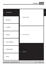
Hardware
© KEB, 2008-02
COMBIVERT R6-S
Seite 1.3 - 5
1
10
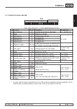
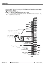
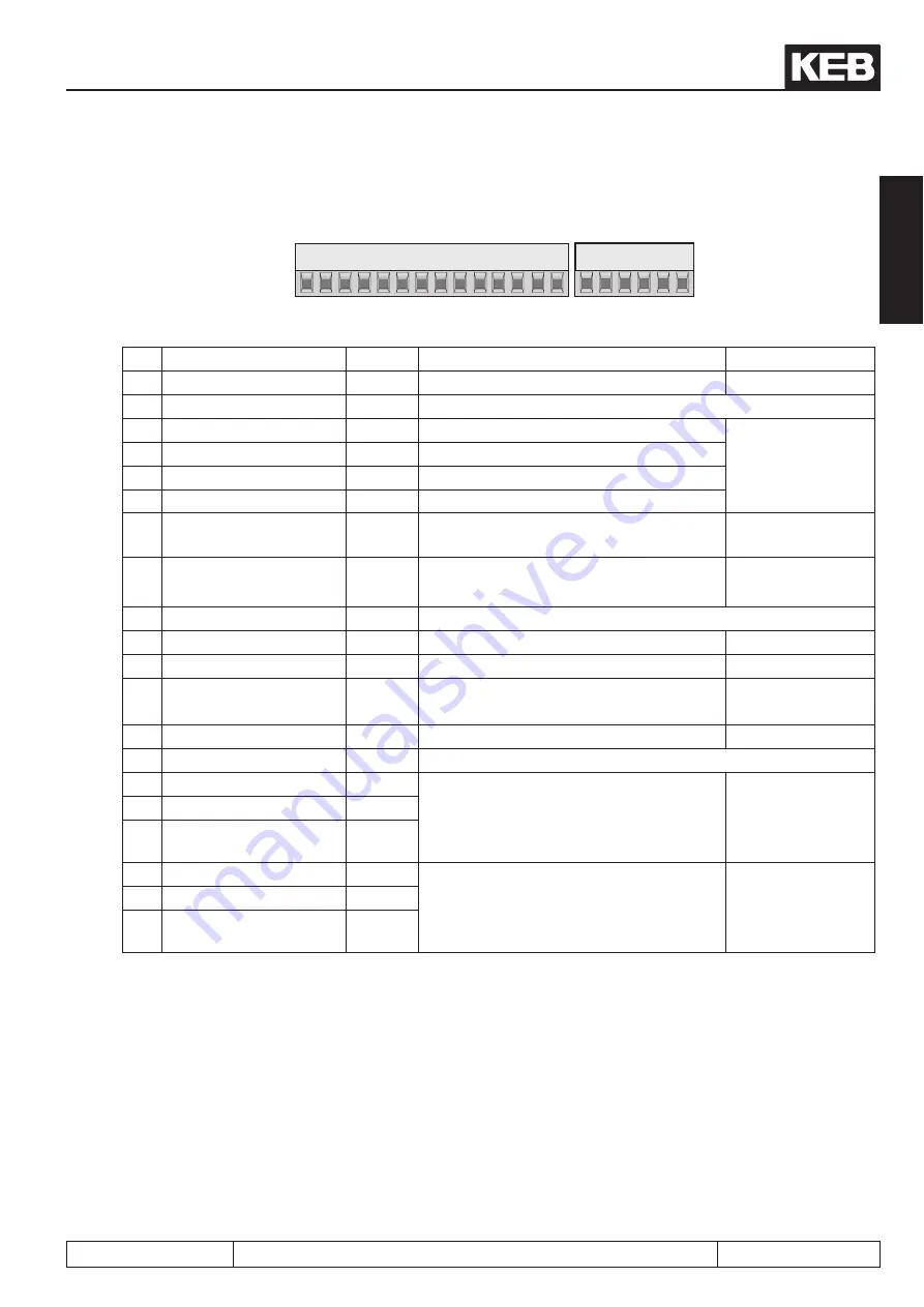
1.3.1.3 Control terminal strip X2A
X2A
Core cross-section 0,14…1,5 mm², tightening torque 0,5 Nm
PIN Function
Name
Description
Specification
10 24 V DC input
Uin
external supply of the control board
23…30 V DC / 1A
11 Mass
COM
Reference potential
12 Digital input 1
ST
Control release / Reset
Ri: 4,4 kΩ
13 Digital input 2
I1
programmable
14 Digital input 3
I2
programmable
15 Digital input 4
I3
programmable
16 Digital in-/output
I/O (I4) Active signal (connection of all R6 at paral-
lel operation in master-slave procedure)
17 24V output
Uout
Voltage supply for in- and outputs
ca. 24 V / max.
100 mA
18 Mass
COM
Reference potential
19 Digital output 1
O1
Transistor output (DC > CP.19)
I
max
: 25 mA
20 Digital output 2
O2
Transistor output (error message)
I
max
: 25 mA
21 Analog output / gain
ANOUT Difference between actual supply frequen-
cy and set supply frequency
1 V pro 0,1 Hz
Difference
22 24V output
Uout
see terminal 17
23 Mass
COM
Reference potential
24 Relay 1 / NO
RLA
Relay output
Ready signal (no error)
max. 30 V DC
*)
0,01…2 A DC
25 Relay 1 / NC
RLB
26 Relay 1 / switching
contact
RLC
27 Relay 2 / NO
FLA
Relay output
(DC > CP.19 and tightened load-shunt)
max. 30 V DC
*)
0,01…2 A DC
28 Relay 2 / NC
FLB
29 Relay 2 / switching
contact
FLC
*) The relay outputs must be operated with max. 48 V DC protective separation voltage to guarantee the CE
standard. After consultation KEB a current of max. 1 A DC is permissible for 120 V AC.
Summary of Contents for combivert R6-S
Page 1: ...APPLICATION MANUAL Mat No Rev 00R6SEA K130 1 A GB KEB COMBIVERT R6 S Version 1 3 ...
Page 2: ...Page 1 1 2 COMBIVERT R6 S KEB 2008 02 Introduction ...
Page 4: ...Page 1 1 4 COMBIVERT R6 S KEB 2008 02 Introduction ...
Page 14: ...Page 1 2 6 COMBIVERT R6 S KEB 2008 02 Product overview ...
Page 28: ...Page 2 1 6 COMBIVERT R6 S KEB 2008 02 Fundamentals ...
Page 34: ...Page 2 2 6 COMBIVERT R6 S KEB 2008 02 Password structure ...
Page 116: ...Page 3 8 2 COMBIVERT R6 S KEB 2008 02 Special functions 3 8 1 Program timer counter 3 8 3 ...
Page 130: ...Page 3 9 10 COMBIVERT R6 S KEB 2008 02 Define CP Parameters ...
Page 140: ...Page4 2 2 COMBIVERT R6 S KEB 2008 02 Start up ...
Page 144: ...Page4 2 6 COMBIVERT R6 S KEB 2008 02 Start up ...
Page 150: ...Page 5 1 6 COMBIVERT R6 S KEB 2008 02 Error assistance ...
Page 158: ...Page 6 1 8 COMBIVERT R6 S KEB 2008 02 Project design ...
Page 160: ...Seite 7 1 2 COMBIVERT R6 S KEB 2008 02 Annex 7 1 1 Keyword index 7 1 3 ...
Page 166: ......
Page 167: ......

