background image

Password structure

© KEB, 2008-02

COMBIVERT R6-S

Page 2.2 - 3

2

10

2.2  Password structure

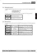
The KEB COMBIVERT is equipped with an extensive password protection. With the individual passwords it is 

possible:


- to change the operating mode


- to set a write protection


- to activate the service mode


Dependent on the actual operation 

mode the password can be entered in the following parameters:

if the CP mode is activated

if the application mode is activated

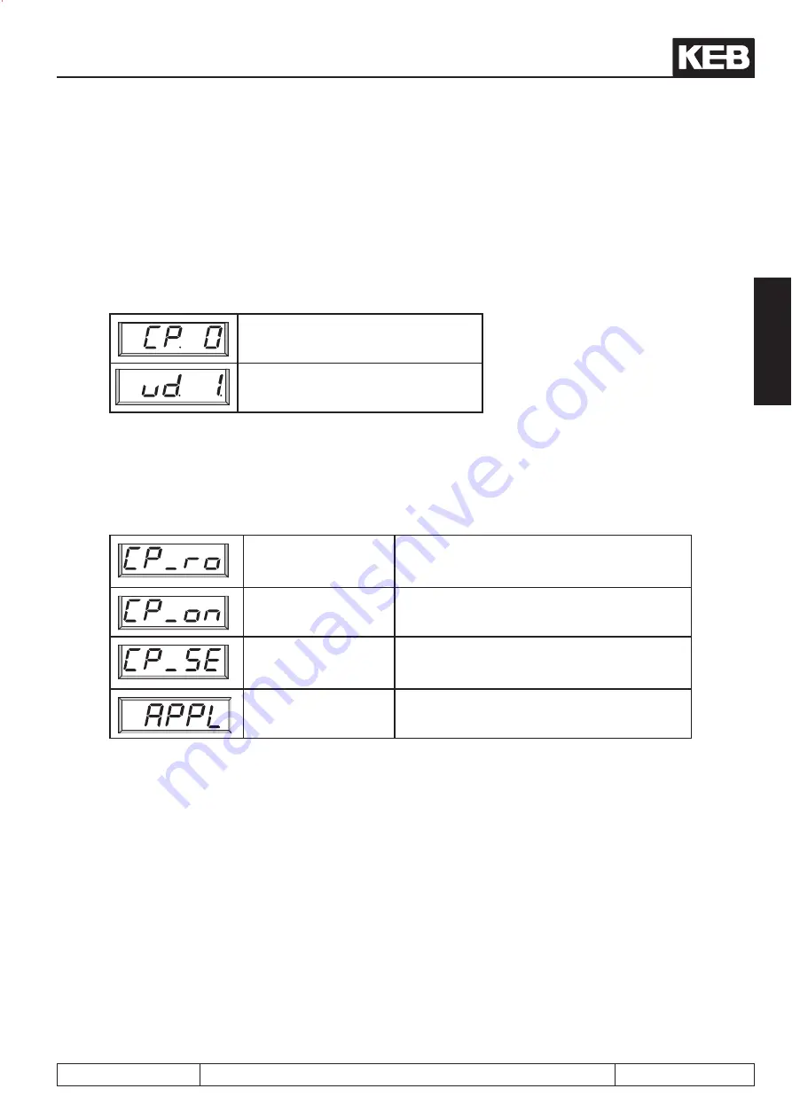
2.2.1  Password levels

The parameter value of the parameters above displays the actual password level. The following displays are 

possible:

CP - read only

Only the customer parameter group is visible, all 

parameters are in read only status, except CP.0  

(see chapter 4.3).

CP - on

Only the customer parameter group is visible. All 

parameters can be changed.

 CP - Service

Like CP-on, however the parameter identification 

is displayed in accordance with its origin parameter 

(see chapter 4.3)

Application

All application parameters are visible and can be 

changed. The CP-Parameters are not visible.

Summary of Contents for combivert R6-S

Page 1: ...APPLICATION MANUAL Mat No Rev 00R6SEA K130 1 A GB KEB COMBIVERT R6 S Version 1 3 ...

Page 2: ...Page 1 1 2 COMBIVERT R6 S KEB 2008 02 Introduction ...

Page 3: ...tion Integration of the KEB COMBIVERT into existing networking A listing of all parameters sorted to parameter groups The parameter description contains addresses value ranges and references to the use All inverter functions with their respective parameters are summarized in this chapter in order to get a simple programming Provides assistance at the initial start up and gives possibilities and te...

Page 4: ...Page 1 1 4 COMBIVERT R6 S KEB 2008 02 Introduction ...

Page 5: ...rameter groups parameter sets 2 1 3 2 1 2 Selection of a parameter 2 1 4 2 1 3 Adjustment of parameter values 2 1 4 2 1 4 ENTER parameters 2 1 5 2 1 5 Not set programmable parameters 2 1 5 2 1 6 Reset of error messages 2 1 5 2 1 7 Reset of peak values 2 1 5 2 1 8 Acknowledge of feedbacks 2 1 5 2 2 Password structure 2 2 3 2 2 1 Password levels 2 2 3 2 2 2 Passwords 2 2 4 2 2 3 Changing the passwor...

Page 6: ... 6 3 4 9 Reset input selection di 09 and neg slope for reset inputs di 10 3 4 8 3 4 10 Assignment of the inputs 3 4 8 3 4 11 Software ST and locking of the control release 3 4 10 3 4 12 Short description digital outputs 3 4 11 3 4 13Output signals hardware 3 4 12 3 4 14 Output filter do 43 do 44 3 4 12 3 4 15 Conditions do 00 do 07 3 4 13 3 4 16 Invert conditions for flags 0 7 do 08 do 15 3 4 15 3...

Page 7: ...y parameters 3 7 3 3 7 3 Indirect and direct set addressing 3 7 3 3 7 4 Copying of parameter sets via keyboard Fr 01 3 7 4 3 7 5 Copy parameter sets via bus Fr 01 Fr 09 3 7 5 3 7 6 Select parameter sets 3 7 6 3 7 7 Locking of parameter sets 3 7 10 3 7 8 Parameter set activation delay deactivation delay Fr 05 Fr 06 3 7 10 3 8 Special functions 3 8 3 3 8 1 Program timer counter 3 8 3 3 9 Define CP P...

Page 8: ...l designs 6 1 3 6 1 1 Control cabinet design calculation 6 1 3 6 1 2 Dimensioning power supply and regenerative units 6 1 5 6 1 3 DC link capacitors of KEB frequency inverters 6 1 6 6 1 4 Dimensioning of decoupling diodes 6 1 6 6 1 5 Overload characteristics 6 1 7 7 Annex 7 1 3 7 1 Search and Find 7 1 3 7 1 1 Keyword index 7 1 3 ...

Page 9: ...uct overview KEB 2008 02 COMBIVERT R6 S Page 1 2 1 1 10 1 Introduction 2 Operation 3 Functions 4 Start up 5 Error Assistance 6 Project Design 7 Annex 1 1 Table of contents 1 2 Product overview 1 3 Hardware ...

Page 10: ...Page 1 2 2 COMBIVERT R6 S KEB 2008 02 Product overview 1 2 1 Preface 1 2 3 1 2 2 Use of power supply and regenerative units 1 2 3 1 2 3 Functional principle 1 2 4 1 2 4 Part code 1 2 5 ...

Page 11: ...flow direction so usually the regenerative energy is dissipated with a brake transistor and braking resistor The overvoltage is limited by this way and thus an error disconnection or destruction of the inverter is avoided The target of the regenerative unit is not to dissipate the regenerative energy into heat but to regenerate the usable energy into the net Condition for this inverters with at le...

Page 12: ...ave modulation The COMBIVERT can synchronize to mains frequency by a sychronization module in front of the commutation throttle or harmonic filter so regenera tion is done synchronously to the mains frequency A sine wave current is formed of it at the harmonic filter The compliance with the requirements in accordance with EN 61000 3 12 is secured only by the harmonic filter If the regenerative pow...

Page 13: ...ling D varnished external fan E varnished special fan Design 0 default R variable size part Design 0 KEB default design 1 alteration Voltage connection type interference suppression KEB standard units 9 3ph 400V AC Housing size E R P Options 1 precharging 3 Precharging DC fuses Control board 0 no control board S control card 1B R5 2B R6 Unit type always R6 1 and 2 digit Unit size ...

Page 14: ...Page 1 2 6 COMBIVERT R6 S KEB 2008 02 Product overview ...

Page 15: ...Hardware KEB 2008 02 COMBIVERT R6 S Seite 1 3 1 1 10 1 Introduction 2 Operation 3 Functions 4 Start up 5 Error Assistance 6 Project Design 7 Annex 1 1 Table of contents 1 2 Product overview 1 3 Hardware ...

Page 16: ...2 Control board 2B R6 1 3 4 1 3 1 3 Control terminal strip X2A 1 3 5 1 3 1 4 Synchronization line X2B 1 3 7 1 3 1 5 Activation of the self holding X2C 1 3 7 1 3 1 6 HSP5 Operator interface X4B 1 3 7 1 3 1 7 Connection for precharging X1B 1 3 8 1 3 1 8 Connection of the control release of the connected inverter 1 3 8 ...

Page 17: ... 1Control board 1B R6 Connection terminals of the control board X2A 10 23 X2A 24 29 X2B X4B 5 4 3 2 1 9 8 7 6 5 4 3 2 1 9 8 7 6 X2A Control terminal strip Install control and mains cable separately X2B Connection synchronization line ST Potential X4B Operator interface No direct PC connection ...

Page 18: ...rd X2A 10 23 X2A 24 29 X1B X2C X2B X4B 5 4 3 2 1 9 8 7 6 5 4 3 2 1 9 8 7 6 X1B Connection precharging Net Potential X2B Connection synchronization line X2C Activation of the line contactor self holding X4B HSP5 interface No direct PC connection X2A Control terminal strip Install control and mains cable se parately ...

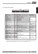
Page 19: ...ts ca 24V max 100mA 18 Mass COM Reference potential 19 Digital output 1 O1 Transistor output DC CP 19 Imax 25mA 20 Digital output 2 O2 Transistor output error message Imax 25mA 21 Analog output gain ANOUT Difference between actual supply frequen cy and set supply frequency 1 V pro 0 1 Hz Difference 22 24V output Uout see terminal 17 23 Mass COM Reference potential 24 Relay 1 NO RLA Relay output Re...

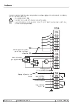
Page 20: ...one side of the inverter onto earth potential Lay control and power cable separately about 10 20cm apart Lay crossings in a right angle in case it cannot be prevented U X2A 10 11 12 13 14 15 16 17 18 16 18 19 20 21 22 23 24 25 26 27 28 29 max 25mADC per digital output Analog output 0 10VDC 5mA max 30VDC 0 01 2A max 30VDC 0 01 2A Active signal for further R6 S units at parallel operation Supply vol...

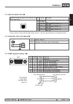
Page 21: ...t X2B at the commutation throttle 1 3 1 5Activation of the self holding X2C X2C 25 24 K1 K1 Mains contactor X2C Activation of the line contactor self holding 1 3 1 6HSP5 Operator interface X4B X4B PIN RS485 Signal Meaning 5 4 3 2 1 9 8 7 6 1 reserved 2 TxD Transmission signal RS232 3 RxD Receive signal RS232 4 A RxD A Receive signal A RS485 5 B RxD B Receive signal B RS485 6 VP Voltage supply 5V I...

Page 22: ...he message ready is set This can be guaranteed by a series connection of the relay R1 of the R6 S units with the control release of the connected converters G1 G2 Regenerative unit COMBIVERT R6 S X2A Control terminal strip 24 Relais 1 NO contact Ready for operation relay 25 Relais 1 CO contact 26 Relais 1 switching contact G3 G4 Frequency inverter COMBIVERT F5 X2A Control terminal strip 16 Control...

Page 23: ...damentals KEB 2008 02 COMBIVERT R6 S Page 2 1 1 2 10 1 Introduction 2 Operation 3 Functions 4 Start up 5 Error Assistance 6 Project Design 7 Annex 2 1 Fundamentals 2 2 Password input 2 3 Network components ...

Page 24: ...oups parameter sets 2 1 3 2 1 2 Selection of a parameter 2 1 4 2 1 3 Adjustment of parameter values 2 1 4 2 1 4 ENTER parameters 2 1 5 2 1 5 Not programmable parameters 2 1 5 2 1 6 Reset of error messages 2 1 5 2 1 7 Reset of peak values 2 1 5 2 1 8 Acknowledge of feedbacks 2 1 5 ...

Page 25: ... and changed if necessary is generally activated only for application adapti on 2 1 1 Parameters parameter groups parameter sets What are parameters parameter groups and parameter sets Parameters are values changeable by the user in a program which affect the program flow A parameter con sists of Parameter designation Parameter value The parameter value indicates the actual adjustment The paramete...

Page 26: ...t non set progammable parameters see 4 1 5 Changes between parameter value FUNC SPEED and parameter designation 2 1 3 Adjustment of parameter values Changing of standard parameters ENTER parameters v a l u e s a r e immediately accepted and stored non volatile a point behind the last digit is displayed during changing the value is accepted and stored non volatile by pressing ENTER START START STAR...

Page 27: ...en by a flashing alarm message The error message can be deleted by pressing the ENTER key so the original value is displayed again Attention Resetting the error message with ENTER is not an error reset i e the error status in the inverter is not reset Thus it is possible to change adjustments before the error reset An error reset is only possible by reset terminal or control release 2 1 7 Reset of...

Page 28: ...Page 2 1 6 COMBIVERT R6 S KEB 2008 02 Fundamentals ...

Page 29: ...rd structure KEB 2008 02 COMBIVERT R6 S Page 2 2 1 2 10 1 Introduction 2 Operation 3 Functions 4 Start up 5 Error Assistance 6 Project Design 7 Annex 2 1 Fundamentals 2 2 Password input 2 3 Network components ...

Page 30: ...Page 2 2 2 COMBIVERT R6 S KEB 2008 02 Password structure 2 2 1 Password levels 2 2 3 2 2 2 Passwords 2 2 4 2 2 3 Changing the password level 2 2 5 ...

Page 31: ... the application mode is activated 2 2 1 Password levels The parameter value of the parameters above displays the actual password level The following displays are possible CP read only Only the customer parameter group is visible all parameters are in read only status except CP 0 see chapter 4 3 CP on Only the customer parameter group is visible All parameters can be changed CP Service Like CP on ...

Page 32: ...Page 2 2 4 COMBIVERT R6 S KEB 2008 02 Password structure 2 2 2 Passwords It can be changed into the respective password level by selection of one of the following passwords Passwords Password level ...

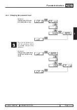
Page 33: ...age 2 2 5 2 10 2 2 3 Changing the password level Example 1 Change from CP mode into application mode The entered password le vels are generally stored non volatile except service password Example 2 Change from application mode into CP read only mode ...

Page 34: ...Page 2 2 6 COMBIVERT R6 S KEB 2008 02 Password structure ...

Page 35: ...k components KEB 2008 02 COMBIVERT R6 S Page 2 3 1 2 10 1 Introduction 2 Operation 3 Functions 4 Start up 5 Error Assistance 6 Project Design 7 Annex 2 1 Fundamentals 2 2 Password input 2 3 Network components ...

Page 36: ... R6 S KEB 2008 02 Network components 2 3 1 Available hardware 2 3 3 2 3 2 RS232 cable PC operator 00 58 025 001D 2 3 3 2 3 3 HSP5 cable PC control board 00 F5 0C0 0010 2 3 4 2 3 4 Interface operator F5 00 F5 060 2000 2 3 4 ...

Page 37: ...2 or RS485 standard F5 Profibus DPoperator Part No 00 F5 060 3000 F5 InterBus operator Part No 00 F5 060 4000 InterBus remote bus connection Part No 00 B0 0BK K001 in connection with Interface Operator F5 CanOpen operator Part No 00 F5 060 5000 F5 Sercos operator Part No 00 F5 060 6000 Diagnostic interface operator Part No 00 F5 0C0 0020 2 3 2 RS232 cable PC operator 00 58 025 001D The cable of 3m...

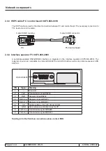
Page 38: ...32 RS484 interface is integrated in the interface operator 00 F5 060 2000 The telegram structure is compatible to protocol DIN 66019 and ANSI X3 28 as well as to protocol expansion DIN 66019 II RS232 RS485 5 4 3 2 1 9 8 7 6 PIN Signal Meaning 1 reserved 2 TxD Transmission signal RS232 3 RxD Receive signal RS232 4 RxD A Receive signal A RS485 5 RxD B Receive signal B RS485 6 VP Supply voltage Plus ...

Page 39: ...n 3 Functions 4 Start up 5 Error Assistance 6 Project Design 7 Annex 3 1 Parameter summary 3 2 Operating and appliance data 3 3 Analog outputs 3 4 Digital in and outputs 3 5 Regenerative adjustments 3 6 Protective functions 3 7 Parameter sets 3 8 Special functions 3 9 Define CP Parameters ...

Page 40: ...Page 3 1 2 COMBIVERT R6 S KEB 2008 02 Parameter overview 3 1 1 Parameter list F5 A E and H 3 1 3 ...

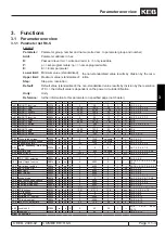
Page 41: ...iod 0A34h rw np E 1 240 1 1 s 3 3 4 3 4 13 cS 00 choke rated voltage 0F00h rw np 0 1000 variable 1 V 3 5 3 4 2 3 cs 01 data commutation choke 0F01h rw np 0 5000 variable 1 A 3 5 3 4 2 33 cS 02 regeneration level 0F02h rw np 100 120 103 1 3 2 6 3 5 4 4 2 4 cS 03 mains frequency max tole rance 0F03h rw np 0 5 5 1 3 6 7 4 2 4 5 1 3 cs 04 control angle 0F04h rw np 0 600 variable 1 3 5 3 3 5 5 4 2 3 4 ...

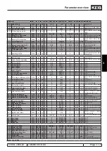
Page 42: ... 0 4095 0 1 3 4 9 3 7 9 In 00 inverter type 0E00h ro np 0 65535 0 1 hex 3 2 4 3 2 12 In 01 DC rated current 0E01h ro np 0 0 6553 5 0 0 0 1 A 3 2 4 3 2 12 In 06 software version 0E06h ro np SW SW SW 0 01 3 2 4 3 2 12 In 07 software date 0E07h ro np SW SW SW 0 1 3 2 4 3 2 12 In 10 serial no date 0E0Ah ro np 0 65535 0 1 3 2 4 3 2 13 3 7 3 In 11 serial no count 0E0Bh ro np 0 65535 0 1 3 2 4 3 2 13 In ...

Page 43: ... 4 3 5 4 4 2 4 ru 19 DC output voltage 0213h ro np 0 1000 0 1 V 3 2 6 3 2 7 ru 20 peak DC voltage 0214h rw np 0 778 0 1 V 3 2 7 ru 21 input terminal state 0215h ro np 0 4095 0 1 3 2 7 3 4 3 3 4 5 ru 22 internal input state 0216h ro np 0 4095 0 1 3 2 7 3 2 18 3 4 3 3 4 5 3 4 14 ru 23 output condition state 0217h ro np 0 255 0 1 3 2 8 3 4 11 3 4 12 ru 24 state of output flags 0218h ro np 0 255 0 1 3...

Page 44: ... 3 2 18 3 2 19 SY 56 start display address 0038h rw np E 0 7FFFH 0200h 1 hex 3 2 20 ud 01 password 0801h cp ro np o P 0 9999 application 1 3 7 3 3 9 3 4 2 34 ud 15 cp selector 080Fh rw np E 1 36 1 1 3 9 3 3 9 4 3 9 6 ud 16 cp address 0810h rw np E 1 off 7FFFH CP Def 1 hex 3 9 3 3 9 4 3 9 6 ud 17 cp set norm 0811h rw np E 1 8191 1 1 3 9 3 3 9 4 3 9 6 ud 18 divisor display morm 0812h rw p E 32767 32...

Page 45: ...ration 3 Functions 4 Start up 5 Error Assistance 6 Project Design 7 Annex 3 1 Parameter summary 3 2 Operating and appliance data 3 3 Analog outputs 3 4 Digital in and outputs 3 5 Regenerative adjustments 3 6 Protective functions 3 7 Parameter sets 3 8 Special functions 3 9 Define CP Parameters ...

Page 46: ...ta 3 2 1 Overview of the ru parameters 3 2 3 3 2 2 Overview of the In parameters 3 2 4 3 2 3 Overview of the Sy parameters 3 2 4 3 2 4 Description of the ru parameters 3 2 5 3 2 5 Description of the In parameters 3 2 12 3 2 6 Description of the Sy parameters 3 2 16 ...

Page 47: ...e ru 03 actual line frequency ru 08 AC phase current L1 ru 09 AC phase current L2 ru 10 AC phase current L3 ru 11 input voltage ru 13 act DC utilization ru 14 peak DC utilization ru 15 DC current ru 16 peak DC current ru 17 AC current ru 18 ref DC voltage ru 19 DC voltage ru 20 peak DC voltage ru 21 input terminal state ru 22 internal input state ru 23 output condition state ru 24 state of output ...

Page 48: ...customer no low In 16 QS no In 22 user parameter 1 In 23 user parameter 2 In 24 last error In 25 error diagnosis In 26 E OC error counter In 27 E OL error counter In 28 E OP error counter In 29 E OH error counter In 30 E OHI error counter 3 2 3 Overview of the SY parameters The SY parameter group contains system specific parameters Following parameters are available SY 02 inverter identifier SY 03...

Page 49: ...e cause and removal are described in chapter 5 Error diagnosis Parameter Addr R PG E Min value Max value Res Default ru 03 Actual line frequency 0203h ro 320 00 320 00 0 01 Hz The actual line frequency is determined during the initialization phase after switching on Slowly changes of the line frequency during the operation are recognized and displayed in ru 03 If the COMBIVERT R6 S is in netof ru ...

Page 50: ... actual DC output current in ampere Parameter Addr R PG E Min value Max value Res Default ru 16 DC output current peak value 0210h rw 0 0 6553 5 0 1 A ru 16 enables to recognize short term peak utilization within an operating cycle For that the highest value of ru 15 is stored in ru 16 The peak value memory can be cleared by pressing the UP DOWN or ENTER key or via bus by writing any value you lik...

Page 51: ...ecimal value is given out for each digital input If several inputs are controlled the sum of the decimal values is indicated Bit Decimal value Input Terminal 0 1 ST prog input control release reset X2A 12 1 2 RST prog input reset no 2 4 F prog input no 3 8 R prog input no 4 16 I1 prog input 1 X2A 13 5 32 I2 prog input 2 X2A 14 6 64 I3 prog input 3 X2A 15 7 128 I4 prog input 4 X2A 16 8 256 IA inter...

Page 52: ...ated Bit Decimal value Output 0 1 switching condition 0 do 00 1 2 Switching condition 1 do 01 2 4 Switching condition 2 do 02 3 8 Switching condition 3 do 03 4 16 Switching condition 4 do 04 5 32 Switching condition 5 do 05 6 64 Switching condition 6 do 06 7 128 Switching condition 7 do 07 Parameter Addr R PG E Min value Max value Res Default ru 24 State of output flags 0218h ro 0 255 1 Display of...

Page 53: ... sets autonomously and can thus start different modes of operation This parameter displays the actual parameter set Independent of it another parameter set can be edited by bus also see chapter 3 7 Parameter Addr R PG E Min value Max value Res Default ru 33 ANOUT1 pre ampl disp 0221h ro 400 400 0 1 This parameter displays the value of the analog signal ANOUT1 in percent before passing the characte...

Page 54: ...G E Min value Max value Res Default ru 43 Timer 1 display 022Bh rw 0 655 35 0 01 The count of the free programmable timer 1 is displayed The display is done either in seconds in hours or in slopes 100 see LE 21 The counter can be adjusted to any chosen value by keyboard or bus The programming of the counter is done with parameters LE 17 LE 21 Parameter Addr R PG E Min value Max value Res Default r...

Page 55: ...ameter Addr R PG E Min value Max value Res Default ru 81 Actual power 0251h ro 3200 0 3200 0 0 1 kW 0 0 ru 81 displays the actual power of the COMBIVERT R6 S Motor power is displayed with positive values generatoric power is displayed with negative values Parameter Addr R PG E Min value Max value Res Default ru 82 Total regen 0252h rw 0 2147483647 1 kWh 0 Counter for the regeneratoric electric wor...

Page 56: ...lue Max value Res Default In 01 DC rated current 0E01h ro 0 0 6553 5 0 1 A Display of the DC rated current in ampere The value is determined from the power circuit identification P ID and cannot be changed Parameter Addr R PG E Min value Max value Res Default In 06 Software version 0E06h ro 1 30 1 30 0 01 Display of the software version number 1 and 2 digit software version e g 1 3X 3 digit specia...

Page 57: ...nformation Parameter Addr R PG E Min value Max value Res Default In 22 User parameter 1 0E16h rw 0 65535 1 0 This parameter is not assigned to any function and is available to the user for input Parameter Addr R PG E Min value Max value Res Default In 23 User parameter 2 0E17h rw 0 65535 1 0 This parameter is not assigned to any function and is available to the user for input Parameter Addr R PG E...

Page 58: ...X X E OP 4 X X X E OH 5 X X X E OHI Example The following values are displayed Set 0 3000 Set 1 2000 Set 2 4023 Set 3 4000 Set 4 7 0000 Explanati on The error that occurs last is stored in set 0 In the table the highest hex value 3 indicates error E OP overvoltage Before it error E OL set 1 2xxx occurs Since the errors are of different types no difference time was stored Error E OH is stored in se...

Page 59: ...us simultaneously it is absolutely necessary to assign different addresses to them since otherwise it leads to communication failures because several COMBIVERT may answer at the same time The descrip tion of the DIN 66019II protocol C0 F5 01I K001 contains further information to this Parameter Addr R PG E Min value Max value Res Default SY 07 Baud rate ext bus PC 0007h rw 0 6 1 3 Following values ...

Page 60: ...word high 0029h rw 0 65535 1 0 The control word is used for status control of the inverter via bus The control word long SY 43 consists of the two 16 bit parameters control word high SY 41 and control word low SY 50 The status word is bit coded Bit Function Value Description 16 I1 1 I1 Corresponding input is set via the control word instead via hardware input These bits are only effective if the b...

Page 61: ... the output terminals and the software outputs digital outputs after the output processing block Corresponds to the display in ru 25 output termi nal state 512 O2 1024 R1 2048 R2 4096 OA 8192 OB 16384 OC 32768 OD Parameter Addr R PG E Min value Max value Res Default SY 43 Control word long 002Bh KB 2147483648 2147483647 1 0 The control word is used for status control of the inverter via bus The co...

Page 62: ...oP 01 rotation source contains the values 8 or 9 the direc tion of rotation is preset via this bit 8 Counter clock wise rotation 4 6 Parameter set 0 Set 0 Selection of the active parameter set if in Fr 02 parameter set source the value 5 control word SY 50 is programmed 16 Set 1 32 Set 2 48 Set 3 64 Set 4 80 Set 5 96 Set 6 112 Set 7 7 reserved 8 Fast stop on off 256 Fast stop Releases fast stop OR...

Page 63: ...et 16 Set 1 32 Set 2 48 Set 3 64 Set 4 80 Set 5 96 Set 6 112 Set 7 7 128 Actual value Setpoint value ru 07 actual value display with a hysteresis of LE 16 freq speed hysteresis has the same value as ru 01 set value dis play 8 256 Fast stop Fast stop is active 9 512 HSP5 bus synchronous Inverter in bus synchronous operation 10 1024 Approach to reference point completed Approach to reference point w...

Page 64: ...esented on switching on the operator Operator parameters can also be adjusted as starting display Only valid addresses are accepted If there is adjusted an invalid address neither in the inverter nor assigned in the operator the operator searches for the next existing address of the parameter group If this parameters is available in the CP mode the setting becomes effective there Otherwise CP 00 i...

Page 65: ...3 Functions 4 Start up 5 Error Assistance 6 Project Design 7 Annex 3 1 Parameter summary 3 2 Operating and appliance data 3 3 Analog outputs 3 4 Digital in and outputs 3 5 Regenerative adjustments 3 6 Protective functions 3 7 Parameter sets 3 8 Special functions 3 9 Define CP Parameters ...

Page 66: ...scription analog output 3 3 3 3 3 2 Output signals 3 3 3 3 3 3 Analog output display ru 33 34 3 3 4 3 3 4 ANOUT 1 Function An 31 An 36 An 41 An 47 3 3 4 3 3 5 Amplifier of the output characteristic An 33 35 An 43 45 An 49 51 3 3 5 3 3 6 ANOUT 1 value An 32 42 48 3 3 6 ...

Page 67: ...sted with An 46 52 Picture 7 2 1 Principle of the analog outputs An 31 41 47 Actual line frequency Δ 2 ru 03 Ref DC voltage 5 ru 18 DC current 6 ru 15 AC current 7 ru 17 Digital with An 32 42 48 8 An xx Power module temperature 12 ru 38 Actual power 26 ru 81 An 31 An 33 An 34 An 35 X2A 21 ANOUT1 X2A 23 AGND 0 100 0 10V ru 34 ru 33 An 41 An 43 An 44 An 45 PWM 100 An 46 An 47 An 49 An 50 An 51 PWM 1...

Page 68: ...e used to display the analog outputs before and after the characteristic amplifier ru 33 ANOUT1 pre ampl display 0 400 ru 34 ANOUT1 post ampl display 0 115 3 3 4 ANOUT 1 Function An 31 An 36 An 41 An 47 These parameters define the process variable which controls the respective output Following adjustments are possible An 31 An 41 An 47 Value Function Standard An 31 10V 100 2 Actual line frequency ...

Page 69: ...output see picture 7 2 2 Function ANOUT1 Value range Resolution Default Amplification An 33 20 00 0 01 1 00 X Offset An 34 100 0 0 1 0 0 Y Offset An 35 100 0 0 1 0 0 Picture 7 2 5 a factory setting no offset gain 1 Output voltage 10V 100 100 100 An 33 An 34 An 35 100 visible range variable to be indicated Invert the analog output An example for the use of the characteristic amplifier is shown in p...

Page 70: ...igh gain the analog output switches in a relative small switching window Calculation of the gain Since the analog output works always to the specified values in 7 2 4 the characteristic can be adjusted with the gain so that the total range of 0 10V is used specified value desired value gain An 33 43 49 3 3 6 ANOUT 1 value An 32 42 48 Analog values for the respective input can be preset in percenta...

Page 71: ...ion 3 Functions 4 Start up 5 Error Assistance 6 Project Design 7 Annex 3 1 Parameter summary 3 2 Operating and appliance data 3 3 Analog outputs 3 4 Digital in and outputs 3 5 Regenerative adjustments 3 6 Protective functions 3 7 Parameter sets 3 8 Special functions 3 9 Define CP Parameters ...

Page 72: ...0 3 4 8 3 4 10 Assignment of the inputs 3 4 8 3 4 11 Software ST and locking of the control release 3 4 10 3 4 12 Short description digital outputs 3 4 11 3 4 13 Output signals hardware 3 4 12 3 4 14 Output filter do 43 do 44 3 4 12 3 4 15 Conditions do 00 do 07 3 4 13 3 4 16 Invert conditions for flags 0 7 do 08 do 15 3 4 15 3 4 17 Selection of the conditions for flags 0 7 do 16 do 23 3 4 15 3 4 ...

Page 73: ...ernal input state ru 22 displays the actual inputs set for further processing The function s which are executed by a programmable input is determined with the input selection of the ap propriate function or di 11 22 The control release ST must be switched generally by hardware for safety reasons Edge triggering inversion and strobe signal can be adjusted but they have no influence Picture 7 3 1 Pr...

Page 74: ...nputs 13 30V DC 0 smoothed Picture 7 3 2 b Digital inputs in NPN control di 00 1 Internal supply COM 24V in ST I1 I2 I3 11 12 13 14 15 10 18 COM 11 12 13 14 15 COM I2 I3 I1 ST PE X2A Ri digital inputs 4 4 kΩ External supply 3 4 3 Set digital inputs per software di 01 di 02 Digital inputs can be set without external circuit with parameter di 01 select signal source and di 02 digital input setting T...

Page 75: ...2 4 F prog input no 3 8 R prog input no 4 16 I1 prog input 1 X2A 13 5 32 I2 prog input 2 X2A 14 6 64 I3 prog input 3 X2A 15 7 128 I4 prog input 4 X2A 16 8 256 IA internal input A no 9 512 IB internal input B no 10 1024 IC internal input C no 11 2048 ID internal input D no Example ST F and IB are controlled displayed value 1 4 512 517 3 4 4 Input terminal state ru 21 internal input state ru 22 The ...

Page 76: ...ERT is controlled with static signals i e an input is set as long as a signal is active But in practice it may happen that a signal is only available temporary but the input shall remain set For this case this or several inputs can be set to input trigger A rising slope with a pulse duration which is longer than the response time of the digital filter is sufficient for switching on Switching off i...

Page 77: ...e the strobe in a kind of gate function In this case the strobe is static i e the input signals are stored as long as the strobe signal is set or the gate is open di 07 Strobe mode di 07 Strobe mode Value Function Description 0 slope active strobe def ault Input states are stored with the rising edge at strobe input and reta ined to the next rising slope 1 static strobe freezing at inactive strobe...

Page 78: ...vidual functions one input can be selected which activates this function b One or several functions can be assigned to each digital input That means in parameters di 11 di 22 function and parameters di 24 di 35 prog function one or several functions can be assigned to each digital input With parameters di 11 di 22 several functions can be assigned to the respective inputs one function can only be ...

Page 79: ...et 0 Fr 11 13 8192 external error trigger error state at the inverter Pn 04 17 131072 start timer 1 Start Stop Timer LE 17 18 262144 reset timer 1 LE 19 19 524288 start timer 2 LE 22 20 1048576 reset timer 2 LE 24 31 2147483648 I function one additional function function is selected Not listed bits are not assigned 1 displays the function related parameter which corresponds to the value in di 11 d...

Page 80: ...e control release can remain controlled with the locking function although if the controlled SPS fails A condition is that the terminal ST is bridged The switching off of an input selection in di 36 is delayed by the time adjusted in di 38 Within this time the locking input must become active selection in di 37 in order to ensure the function Bild 3 4 11c Software ST locking of the control release...

Page 81: ...4 23 8 24 16 25 32 26 64 27 128 1 20 1 8 8 1 8 8 1 8 8 1 8 8 1 8 8 1 8 8 do 41 8 8 8 8 1 1 21 2 22 4 23 8 24 16 25 32 26 64 27 128 8 8 0 1 2 3 4 5 6 7 8 9 10 11 12 13 14 15 16 17 18 19 20 21 22 23 z 1 z 1 do 43 do 44 1 1 1 1 1 1 1 1 1 1 1 1 1 1 1 1 1 1 1 1 1 1 1 1 1 1 1 1 1 1 1 1 1 1 1 1 1 1 1 1 1 1 1 1 1 1 1 1 1 1 1 1 1 1 1 1 8 do 51 0 1 2 3 O1 O1 O1 O2 O1 R1 O1 R2 0 4 8 12 O2 O1 O2 O2 O2 R1 O2 R...

Page 82: ...e of the linkage AND OR Parameter do 42 serves for inverting one or several outputs The output signals are assigned to the terminals with do 51 ru 80 displays the digital output state ru 25 displays the output terminal state The internal outputs OA OD are directly connected with the internal inputs IA ID 3 4 13Output signals hardware Picture 7 3 13a Transistor outputs Picture 7 3 13b Relay outputs...

Page 83: ...r in case of warning can be adjusted with Pn 08 warning OL stop mode 8 Pre warning power stage over heating Overtemperature pre warning OH Depending on the power unit the COM BIVERT switches off between 60 95 C heat sink temperature The pre warning is output if the OH warning level Pn 11 is reached default 70 C The behaviour in case of warning can be adjusted with Pn 10 warning OL stopping mode 9 ...

Page 84: ... OR linked ru 22 61 Inputs NAND linked ru 22 62 Inputs NOR linked ru 22 63 Absolute value ANOUT1 level Value of ANOUT1 amount of ru 34 ANOUT1 post ampl display higher than the switching level 65 ANOUT1 level ANOUT1 ru 34 ANOUT1 post ampl display higher than the switching le vel 73 Value actual power level Value ru 81 actual power switching level 74 Actual power level ru 81 actual power switching l...

Page 85: ... 3 4 17Selection of the conditions for flags 0 7 do 16 do 23 Parameters do 16 do 23 serve for the selection of the 8 preassigned conditions The selection for each flag occurs separately whereby it can be selected between none and up to all 8 conditions The value for the se lected condition must be entered in do 16 do 23 according to picture 3 4 15 If several conditions shall be selected the sum mu...

Page 86: ... 25 do 32 each of the 8 flags Bit 0 7 of logic step 1 can be inverted separately Any flag can be used as non flag by this function The parameter is bit coded The value for the flag to be in verted must be entered in do 25 do 32 according to picture 3 4 19 If several flags shall be inverted the sum must be formed 3 4 20Selection of flags do 33 do 40 A selection of flags from the first logic step ca...

Page 87: ...e means all selected flags must be set before the output switches Picture 3 4 21a Linking the outputs 0 1 0 1 0 1 Bit 0 Bit 1 Bit 7 O1 O2 OD do 41 1 1 1 8 8 8 do 33 do 34 do 40 As shown in picture 3 4 22b the outputs can be inverted again with parameter do 42 after linking The parame ter is bit coded i e in accordance with the following table the associated value to the output must be entered If s...

Page 88: ...ut Name Function Decimal values O1 Transistor output 1 O2 Transistor output 2 R1 Relay output 4 R2 Relay output 8 OA Internal output 16 OB Internal output 32 OC Internal output 64 OD Internal output 128 3 4 23Hardware output allocation do 51 The output signals are assigned to output terminals O1 O2 R1 and R2 with parameter do 51 Allocation is done according to the following table do 51 Hardware ou...

Page 89: ...tion 3 Functions 4 Start up 5 Error Assistance 6 Project Design 7 Annex 3 1 Parameter summary 3 2 Operating and appliance data 3 3 Analog outputs 3 4 Digital in and outputs 3 5 Regenerative adjustments 3 6 Protective functions 3 7 Parameter sets 3 8 Special functions 3 9 Define CP Parameters ...

Page 90: ... KEB 2008 02 Regenerative adjustments 3 5 1 Operating mode 3 5 3 3 5 2 Setting of the choke rating data 3 5 3 3 5 3 Activate regeneration 3 5 4 3 5 4 Deactivate regeneration 3 5 4 3 5 5 Optimize the regenerative current 3 5 4 ...

Page 91: ...it as ma ster With changing of the adjustment of Pn 19 the parameterizing of cS 00 cS 01 and cS 04 for the KEB standard commutation choke or the KEB standard harmonic filter is preset When using KEB products no further pa rameter setting is necessary The values of cS 00 cS 01 and cS 04 are overwritten at external products with response of Pn 19 If the R6 is operated as a master I4 X2A 16 is automa...

Page 92: ...n cS 02 which is per cental related to the reference voltage Parameter Addr R PG E Min value Max value Res Default cS 02 Regeneration level 0F02h rw 100 120 1 103 3 5 4 Deactivate regeneration If the active power exceeds the level specified in cS 06 the modulation is switched off after puls off delay cS 05 Parameter Addr R PG E Min value Max value Res Default cS 05 Puls off delay 0F05h rw 0 32000 ...

Page 93: ...ax value Res Default cS 04 Control angle 0F04h rw 0 600 1 var The regenerative current can be optimized with an oscilloscope by the control angle cS 04 The following pictures give an overview of the current at different control angles 1 Bad current adjustment with smaller angle diode loss Over undershoot of the current 2 Optimal current flow ...

Page 94: ...Page3 5 6 COMBIVERT R6 S KEB 2008 02 Regenerative adjustments 3 Bad current adjustment with high angle high peak currents ...

Page 95: ...on 3 Functions 4 Start up 5 Error Assistance 6 Project Design 7 Annex 3 1 Parameter summary 3 2 Operating and appliance data 3 3 Analog outputs 3 4 Digital in and outputs 3 5 Regenerative adjustments 3 6 Protective functions 3 7 Parameter sets 3 8 Special functions 3 9 Define CP Parameters ...

Page 96: ...3 6 1 7 Bus error 3 6 6 3 6 1 8 Set selection error 3 6 6 3 6 1 9 Hardware error 3 6 6 3 6 1 10 Regeneration error 3 6 7 3 6 2 Response to malfunction messages 3 6 7 3 6 2 1 Selection of the response 3 6 7 3 6 2 2 General fault reset Pn 15 3 6 8 3 6 3 Automatic restart 3 6 9 3 6 3 1 Undervoltage error E UP 3 6 9 3 6 3 2 Overvoltage error E OP 3 6 9 3 6 3 3 Overcurrent error E OC 3 6 9 3 6 3 4 Malf...

Page 97: ...Display in parameter ru 00 Error Watchdog E buS If a digital output is program med on a fault signalling relay the relay switches Beispiel 3 operating condition programmed as malfunction The reaction of the bus monitor watchdog shall trigger a malfunction Programming Pn 05 Watchdog re sponse 0 error no auto restart Display in parameter ru 00 Error Watchdog E buS If a digital output is programmed o...

Page 98: ...16 99 Error warning overload Ixt E OP 1 Error overvoltage E PU 12 Error defective in power unit E Puch 50 Error power unit code changed E PucI 49 Error power circuit unknown E PUIN 14 Error power unit coding E SEt A SEt 39 102 Error warning set E SYn 59 Error synchronization E UP 2 Error underpotential F nEt 40 Error mains frequency 3 6 1 1Undervoltage Error Undervoltage E UP is triggered if the D...

Page 99: ...re normal again E nOH and is therefore resettable With Pn 11 Heat sink overtemperature warning level a level of between 0 C and 90 C can be set at which the pre warning is triggered The response to the warning message is set with Pn 10 Heat sink overtempera ture response Internal overtemperature The interior temperature monitoring protects the COMBIVERT against malfunctions caused by too high temp...

Page 100: ...eter set selection E Set is triggered For Pn 18 1 5 a malfunction 102 Warning Set selection error A Set is generated For Pn 18 6 Function disabled the drive continues running in the old set without message 3 6 1 9Hardware error On some inverter types monitorings for the internal hardware e g switch mode power supply or loading shunt relay are integrated If one of these monitoring circuits reports ...

Page 101: ... mode Other errors switch off the modulation but a pre warning can be generated prior to their triggering In the time between the pre warning signal and the triggering of the error the drive can be stopped The response is pro grammable overload Pn 08 warning OL stop mode Heat sink overtemperature Pn 10 Heat sink overtemperature response internal overtemperature Pn 16 Internal overtemperature respo...

Page 102: ...d the error overtemperature is never triggered No message via digital output possible For the malfunction internal overtemperature there are two response options as well Pn 16 Internal overtemperature Value Description 6 Warning via digital output The monitoring of the internal temperature is active but the drive does not execute an automatic abnormal stop A pre warning signal can be issued via a ...

Page 103: ...ion for the automatic restart E UP Pn 00 is operation on a bad power grid where sporadic voltage dips are to be expected With this function the application continues running as soon as the mains voltage is sufficiently high again 3 6 3 2Overvoltage error E OP The error overvoltage usually occurs at deceleration in connection with an overcurrent error At automatic re start the blocking time modulat...

Page 104: ...g mode Value Description 0 Master with commutation choke For high power regenerative units can be parallel connected Here a device must be specified as master All further are adjusted as slave Single units are always master The coupling of the regenerative units is made by terminals X2A 1618 since this is a fast digital input 1 Master with harmonic filter 2 Slave with commutation choke 3 Slave wit...

Page 105: ... Functions 4 Start up 5 Error Assistance 6 Project Design 7 Annex 3 1 Parameter summary 3 2 Operating and appliance data 3 3 Analog outputs 3 4 Digital in and outputs 3 5 Regenerative adjustments 3 6 Protective functions 3 7 Parameter sets 3 8 Special functions 3 9 Define CP Parameters ...

Page 106: ...meters 3 7 3 3 7 3 Indirect and direct set addressing 3 7 3 3 7 4 Copying of parameter sets via keyboard Fr 01 3 7 4 3 7 5 Copy parameter sets via bus Fr 01 Fr 09 3 7 5 3 7 6 Select parameter sets 3 7 6 3 7 7 Locking of parameter sets 3 7 10 3 7 8 Parameter set activation delay deactivation delay Fr 05 Fr 06 3 7 10 ...

Page 107: ...ly visible Always the same value is valid for all non set programmable parameters independent of the selected parameter set The following parameters are not set programmable SY Parameter ud 01 17 ru Parameter Fr 02 04 07 09 11 di Parameter An 41 52 In Parameter exception In 24 and 25 LE 17 26 Pn 00 19 3 7 2 Security parameters The security parameters include the baud rate inverter address hour cou...

Page 108: ... adjusted with the keys UP Down at blinking dot next to the parameter set number The active A parameter set may not be adjusted as target set when copying If the target set is 0 only the programmable parame ters are overwritten The source set is adjusted with the keys UP Down The copy process is started with Enter Copy process is only pos sible with open control release or error otherwise I_op inv...

Page 109: ...set 0 exception system and security parameters 1 7 1 dEF_S Default values are copied in all set programmable parameters of the target set exception system and security parameters All 2 dEF_A Default values are copied in all parameters of all sets exception system and security parameters 0 3 ini_S Default values are copied in all parameters of set 0 exception security parameters 1 7 3 ini_S Default...

Page 110: ...ATTENTION The valence at Fr 02 2 4 is generally ID IC ST The sequence mentioned above refers to the priority Fr 02 Parameter set source As seen in picture 3 7 6 Fr 02 determines whether the parameter set selection is done or switched off via key board bus Fr 04 terminal strip or via control word SY 43 50 The selection is activated by pressing Enter Fr 02 Parameter set source Value Function 0 Set s...

Page 111: ...set source errors Fr 10 Parameter set input selection Bit Value Input Terminal 0 1 1 ST prog input control release reset X2A 12 1 2 RST prog input reset no 2 4 F prog input forward no 3 8 R prog input reverse no 4 16 I1 prog input 1 X2A 13 5 32 I2 prog input 2 X2A 14 6 64 I3 prog input 3 X2A 15 7 128 2 I4 prog input 4 X2A 16 8 256 IA internal input A no 9 512 IB internal input B no 10 1024 IC inte...

Page 112: ...source errors the valence of the programmed inputs for set source is increasing ID IC IB IA I4 I3 I2 I1 R F RST ST Example 1 set 0 7 shall be selected with 3 inputs I1 I2 and I3 1 Set parameter Fr 07 to value 148 2 Set Fr 02 to value 2 set source binary coded via terminal strip I3 I2 I1 Input F I1 I4 t Set 0 Set 1 Set 2 Set 3 Set 4 Set 5 Set 6 Set 7 2 21 20 Set 0 0 0 0 0 0 1 1 0 2 0 2 0 2 1 3 4 0 ...

Page 113: ... 07 to value 2672 2 Set Fr 02 to value 3 set source input coded via terminal strip Id IB I3 I2 I1 Set Set 0 1 2 3 4 5 I1 I2 I3 IB ID Set Set Set Set Set Set Fr 02 3 4 0 0 0 0 0 0 0 0 0 0 0 1 1 1 0 0 0 2 0 2 2 0 0 3 0 0 3 3 0 4 0 0 0 4 4 5 0 0 0 0 5 5 5 0 3 0 0 3 5 5 0 3 0 1 1 5 Reset to set 0 input selection Fr 11 Parameter Fr 11 defines an input independent of the actual parameter set it can be s...

Page 114: ...ameters with which the activation of a new set is delayed Fr 05 with which the deactivation of an old set is delayed Fr 06 At set changeover the switch off time of the old set and the switch on time of the new set are added Picture 3 7 8 Activation delay and deactivation delay Actual set Default set 1 2 3 4 5 6 Set1 Set3 Set2 Set1 Set3 Set2 Set0 Set0 Example 1 Activation delay set 3 of 2s on off 2...

Page 115: ... 3 Functions 4 Start up 5 Error Assistance 6 Project Design 7 Annex 3 1 Parameter summary 3 2 Operating and appliance data 3 3 Analog outputs 3 4 Digital in and outputs 3 5 Regenerative adjustments 3 6 Protective functions 3 7 Parameter sets 3 8 Special functions 3 9 Define CP Parameters ...

Page 116: ...Page 3 8 2 COMBIVERT R6 S KEB 2008 02 Special functions 3 8 1 Program timer counter 3 8 3 ...

Page 117: ...d input for that The current timer content is displayed in ru 43 44 Switching condition 37 38 is set with reaching an adjustable switching level LE 00 07 It can be used to set an output Picture 7 15 4 Timer programming Switching condition 37 Timer 1 Level A is being set Timer value level LE 0 LE 7 Is a reset condition of LE 20 or LE 19 met Timer counts up to maximum value down to 0 if a condition ...

Page 118: ...timer value by 0 01 3 positive slope T1 I3 T2 I4 A rising slope on I3 for timer 1 or I4 for timer 2 incre ases decreases the timer value by 0 01 4 7 reserved 3 4 Counting direc tion 0 Upward The counting direction of the timer is always upwards 24 downwards Timer start condition LE 18 LE 23 The conditions when the timer is started can be selected from the following table The individual conditions ...

Page 119: ...the clock source is changed during the running time the counter content is maintained but is interpreted according to the new clock source Timer reset input selection LE 19 LE 24 The inputs which reset the timer can be defined with the following table The individual inputs are OR operated i e if one of the specified inputs is triggered the timer jumps back to zero If a starting and reset condition...

Page 120: ...operated Bit No Decimal value condition 0 1 Modulation on 1 2 Modulation off 2 4 reserved 3 8 Change of parameter set 4 16 Power On Reset Comparison level 0 7 LE 00 LE 07 LE 00 LE 07 define the level for the switching conditions 37 38 timer level If the timer exceeds the adjusted value the switching condition is set A level in the range of 10 737 418 24 to 10 737 418 23can be adjusted But only val...

Page 121: ...on 3 Functions 4 Start up 5 Error Assistance 6 Project Design 7 Annex 3 1 Parameter summary 3 2 Operating and appliance data 3 3 Analog outputs 3 4 Digital in and outputs 3 5 Regenerative adjustments 3 6 Protective functions 3 7 Parameter sets 3 8 Special functions 3 9 Define CP Parameters ...

Page 122: ...Page 3 9 2 COMBIVERT R6 S KEB 2008 02 Define CP Parameters 3 9 1 Overview 3 9 3 3 9 2 Assignment of the CP Parameters 3 9 4 3 9 3 Example 3 9 6 3 9 4 Variable standardization 3 9 7 ...

Page 123: ...plication mode Service mode Reading writing read only Drive mode Password CP mode Address Set norm Address Address Set norm Set norm ud 15 determines the CP Parameter to be processed With ud 16 and ud 17 the CP Parameter is defined by its address the respective set and the display norm Dependent on the adjusted password CP 00 or ud 01 the adjusted parameter is directly displayed in the service mod...

Page 124: ... Define set selection for direct set addressing Bit 0 7 determine the set selection for direct set programming i e all selected sets gets the same value deter mined by the CP Parameter If direct set programming bit 8 9 is selected at least one set must be selected otherwise error message set invalid is displayed in the CP menue Bit 7 6 5 4 3 2 1 0 Value Set 0 0 0 0 0 0 0 0 0 no Data invalid if bit...

Page 125: ...21 it is possible to define up to seven different user standardizations below in this chapter Bit 12 11 10 Value Function 0 0 0 0 Use standardization of the parameter 0 0 1 1024 Display standardization of parameters ud 18 21 of set 1 0 1 0 2048 Display standardization of parameters ud 18 21 of set 2 1 1 1 7168 Display standardization of parameters ud 18 21 of set 7 ...

Page 126: ...LE 00 in set 3 1 ud 15 1 CP 01 ud 16 0203h Parameter address for ru 03 ud 17 256 Display in the active set 2 ud 15 2 CP 02 ud 16 0D00h Parameter address for LE 00 ud 17 4 Setting in set 2 3 ud 15 3 CP 03 ud 16 0D00h Parameter address for LE 00 ud 17 8 Setting in set 3 4 ud 15 4 CP 04 ud 16 1 off CP 04 is faded out ud 17 xxx ud 17 is without function Set all other parameters like CP 4 to off that t...

Page 127: ...fset 32767 ud 18 divisor 32767 CP xx ud 19 x unit selected parameter ud 20 x ud 18 Inverted For the selected parameter either non standardized value or standardized value resolution is used ud 18 Divisor display norm Adjusts the divisor in the range of 32767 default 1 The parameter is set programmable ud 19 Multiplier display norm Adjusts the multiplier in the range of 32767 default 1 The paramete...

Page 128: ...ity Value Unity Value Unity Value Unity 0 no 16 km h 32 K 48 lbin 1 mm 17 1 min 33 mW 49 in s 2 cm 18 Hz 34 W 50 ft s 3 M 19 kHz 35 kW 51 ft min 4 km 20 mV 36 inc 52 ft s 5 G 21 V 37 53 ft s 6 kg 22 kV 38 kWh 54 MPH 7 us 23 mW 39 mH 55 kp 8 ms 24 W 40 56 psi 9 s 25 kW 41 57 F 10 h 26 VA 42 in 58 11 Nm 27 kVA 43 ft 59 12 kNm 28 mA 44 yd 60 13 m s 29 A 45 oz 61 14 m s2 30 kA 46 lb 62 15 m s3 31 C 47...

Page 129: ...64 ud 19 selected parameter ud 20 x ud 18 CP xx free The non standardized value is used for the selected parameter non standardized value standardized value resolution Table 3 display bit 8 11 Value Display 0 0 decimal places 256 1 decimal place 512 2 decimal places 768 3 decimal places 1024 4 decimal places 1280 variable decimal places 1536 Hexadecimal free ...

Page 130: ...Page 3 9 10 COMBIVERT R6 S KEB 2008 02 Define CP Parameters ...

Page 131: ...Start up KEB 2008 02 COMBIVERT R6 S Page 4 1 1 4 10 1 Introduction 2 Operation 3 Functions 4 Start up 5 Error Assistance 6 Project Design 7 Annex 4 1 Preparatory measures 4 2 Start up ...

Page 132: ...Page 4 1 2 COMBIVERT R6 S KEB 2008 02 Start up 4 1 1 After unpacking the goods 4 1 3 4 1 2 Installation and connection 4 1 3 4 1 3 Checklist prior to start up 4 1 3 4 1 4 Safety instructions 4 1 4 ...

Page 133: ...or complete delivery following measures are to be carried out Visual control for transport damage Should any external damages to the KEB COMBIVERT be visible get in tough with your forwarding agent and return the unit with a corresponding report to KEB 4 1 2 Installation and connection Installation and connection instructions as well as EMC conform installation are found in the instruction manu al...

Page 134: ...e of power failure at regenerative operation Therefore a dangerous high tension can exist in the unit after switching off the supply system Before working with the unit check the isolation from supply by measurements in the unit Care should be taken to ensure correct and safe operation to minimise risk to personnel and equipment Only Qualified Electro Perso nnel All work from the transport to inst...

Page 135: ... Note Capacitor Discharge Time Before any installation and connection work the system must be switched off and secured After clearing the DC link capacitors are still charged with high voltage for a short period of time The unit can be worked on again after it has been switched off for 5 minutes Secure Isolation The terminals of the control terminal strip are securely isolated in accordance with E...

Page 136: ...struction of the components by the equalizing currents Prevent Disturbances A trouble free and safe operation of the COMBIVERT R6 is only guaranteed when the con nection instructions below are strictly followed Incorrect operation or damage may result from incorrect installation Pay attention to mains voltage Install power cables and control cables separately 15 cm separation Use shielded twisted ...

Page 137: ...ker If personnel protection of the system is required the COMBIVERT R6 S must be protected according to EN61800 5 1 3 phase inverters with B6 bridge rectifier by RCMA s with separation used privile ged or RCD s type B all current sensitive FI s The tripping current should be 300mA or more in order to avoid a premature triggering by discharge currents about 200mA Dependent on the load the length of...

Page 138: ...principle of the protective elements Mains to further subdivisions Outlet 1 Outlet 2 Outlet 3 Level 1 Level 2 Type A Type A RCD Type A sel T RCMA RCD Type B Isolator according to EN60947 2 To further consumers that do not pre vent the tripping of the FI To the consumers not compatible with FI ...

Page 139: ...Start up KEB 2008 02 COMBIVERT R6 S Page 4 2 1 4 10 1 Introduction 2 Operation 3 Functions 4 Start up 5 Error Assistance 6 Project Design 7 Annex 4 1 Preparatory Measures 4 2 Start up ...

Page 140: ...Page4 2 2 COMBIVERT R6 S KEB 2008 02 Start up ...

Page 141: ...ents The units are not short circuit proof without corresponding dimensioned fuses Exceeding of the max rechargeable DC link capacity can lead to a defect A load removal in the DC link circle may be done only after the message ready The wiring must be checked before start up particularly the wiring of the control release of the connected inver ters see page 1 3 8 No parameterizations are needed fo...

Page 142: ...ls off level CP 32 If the actual power ru 81 CP 13 exceeds the defined value in cS 06 CP 32 the modulation is switched off after expiration of the adjusted time in cS 05 The parameter settings can usually be left at the default settings 4 2 2 R6 S operation only as regenerative unit Generally also for operating mode regeneration all relevant parameters of the regenerative unit are preset when usin...

Page 143: ...lication can be determined as follows Start up the drive based on the default values and the adjustment via Pn 19 CS 33 Regenerative operation of the drive e g deceleration process Stop the drive LS control release at R6 is active R6 remains in status rEGEn Read actual power ru 81 CP 13 and enter the value plus one offset of approx 10 in cS 06 CP 32 R6 changes into status Stb Check adjustment R6 m...

Page 144: ...Page4 2 6 COMBIVERT R6 S KEB 2008 02 Start up ...

Page 145: ...Error assistance KEB 2008 02 COMBIVERT R6 S Page 5 1 1 5 1 Introduction 2 Operation 3 Functions 4 Start up 5 Error Assistance 6 Project Design 7 Annex 5 1 Error search ...

Page 146: ...Page 5 1 2 COMBIVERT R6 S KEB 2008 02 Error assistance 5 1 1 General 5 1 3 5 1 2 Error messages and their causes 5 1 3 ...

Page 147: ...ndensation takes place 5 1 2 Error messages and their causes At KEB COMBIVERT error messages are always represented with an E and the appropriate error in the display Error messages cause the immediate deactivation of the modulation Restart possible only after reset or autoreset Malfunction are represented with an A and the appropriate message Reactions to malfunctions can vary Status messages hav...

Page 148: ...circuit at the output ground fault overload too high e g deceleration ramp too high at the inverter wrong parameterization E OH Error Power module temperature 8 Overtemperature of power module Error can only be reset at E nOH if the temperature has dropped by at least 5 C Causes insufficient air flow at the heat sink soiled ambient temperature too high ventilator clogged E OHI Error Interior tempe...

Page 149: ...nOH no ABN STOP Power module temperature 88 The heat sink temperature is again below the adjusted warning level A nOHI no ABN STOP Interior temperature 92 The temperature in the interior of the inverter is again below the warning threshold A nOL no ABN STOP Overload 98 Warning no more overload OL counter has reached 0 warning overload can be reset A OH Warning Power module temperature 89 A level c...

Page 150: ...Page 5 1 6 COMBIVERT R6 S KEB 2008 02 Error assistance ...

Page 151: ...Project design KEB 2008 02 COMBIVERT R6 S Page 6 1 1 6 1 Introduction 2 Operation 3 Functions 4 Start up 5 Error Assistance 6 Project Design 7 Annex 6 1 General designs ...

Page 152: ...sign 6 1 1 Control cabinet design calculation 6 1 3 6 1 2 Design of power supply and regenerative units 6 1 5 6 1 3 DC link capacitors of KEB frequency inverters 6 1 6 6 1 4 Dimensioning of decoupling diodes 6 1 6 6 1 5 Overload characteristics 6 1 7 ...

Page 153: ...5 HF side mounted filter size 25 HF side mounted filter size 19 7 Frequency inverter 8 if necessary external DC fuses 9 Motor lines 10 A Protective Earth PE on the moun ting plate power circuit 10b Protective Earth PE on the moun ting plate control circuit 10c Equipotential bonding with the housing earth 11 Mains connection power circuit 11 A Mains connection control circuit 12 Control lines Large...

Page 154: ...case regeneration approx 12 THD Several R6 units can be switched parallelly to increase the supply and regenerative power The following basic requirements must be met for the operation as power supply and regenerative unit stan dard operating mode The sum of the DC link capacities of the connected inverters may not exceed the max permissible DC link capacity of the R6 units The maximum motor DC lo...

Page 155: ...city R6 S Dimensioning of the power supply and regenerative unit Only regeneration Decouple R6 S Acquire PM PMmax t1 T ηM ηG ηFU Calculate ILG ILGmax IDCmax ILGmax Choose bigger unit or parallel processing of R6 S n IDC n IDCmax t1 60s Regenerative unit capable T 300s IDC ILG yes yes no yes no yes no yes no Acquire CZK_all CZK_all CZK_max Acquire PM PMmax t1 T ηM ηG ηFU Calculate ILM ILMmax IDCmax...

Page 156: ...µF 19 2700µF 20 16500µF 20 3900µF 21 19800µF 21 4950µF special version 22 4950µF 23 6350µF 24 8400µF 25 9900µF 26 11700µF 27 14100µF special version 6 1 4 Dimensioning of decoupling diodes R6 S Material number Type Volume Ta C Th C Rha K W 15 0090147 3500 1600V 80A 2 45 90 1 50 19 0090147 4101 1600V 120A 2 45 90 0 84 25 0090147 6009 1600V 560A 2 45 90 0 19 29 0090147 6009 1600V 560A 2 x 2 45 90 0 ...

Page 157: ... reduction Decremental time for OL release s 0 20 40 60 80 100 120 140 160 180 200 220 240 0 10 20 30 40 50 60 70 80 90 100 110 Load OL release time at load increase OL release time s 0 20 40 60 80 100 120 140 160 180 200 220 240 260 280 300 320 100 105 110 115 120 125 130 135 140 145 150 155 160 165 170 Load ...

Page 158: ...Page 6 1 8 COMBIVERT R6 S KEB 2008 02 Project design ...

Page 159: ...Annex KEB 2008 02 COMBIVERT R6 S Seite 7 1 1 7 1 Introduction 2 Operation 3 Functions 4 Start up 5 Error Assistance 6 Project design 7 Annex 7 1 Search and Find ...

Page 160: ...Seite 7 1 2 COMBIVERT R6 S KEB 2008 02 Annex 7 1 1 Keyword index 7 1 3 ...

Page 161: ...3 2 3 Automatic 3 2 18 3 6 4 3 6 9 4 1 6 restart 3 4 12 3 4 13 3 6 3 3 6 4 3 6 7 3 6 8 3 6 9 5 1 5 AUX display 3 2 3 3 2 4 3 2 5 3 2 10 3 2 13 3 2 14 3 2 17 3 2 19 3 2 20 3 3 2 3 3 3 3 3 4 3 4 8 3 4 13 3 4 1 4 3 7 3 3 8 3 3 8 5 3 9 3 3 9 5 3 9 6 3 9 7 5 1 3 Function 1 3 5 1 3 7 3 2 16 3 2 18 3 3 2 3 3 4 3 3 5 3 4 7 3 4 9 3 4 10 3 4 13 3 4 14 3 4 18 3 6 4 3 6 6 3 6 8 3 7 6 3 9 4 3 9 5 3 9 9 B Binar...

Page 162: ...3 7 7 Fr 05 3 7 10 Fr 06 3 7 10 Fr 07 3 4 9 3 7 7 3 7 8 3 7 9 Fr 09 3 7 3 3 7 5 3 9 4 Fr 10 3 7 7 Fr 11 3 4 9 3 7 9 Fundamentals 2 1 3 2 2 1 2 3 1 G Gear factor set programming 3 7 5 H Harmonic filter 1 2 3 1 2 4 3 5 3 4 2 3 4 2 4 6 1 4 Heat sink overtemperature 3 6 5 3 6 7 HSP5 cable 2 3 4 HSP5 cable 2 3 4 Hysteresis 3 4 14 3 4 15 I Incremental encoder input 1 3 5 2 2 1 2 3 1 3 2 3 5 1 4 3 2 5 3 ...

Page 163: ... 3 3 4 6 3 4 7 3 4 8 3 4 9 3 4 10 3 4 12 3 4 15 3 4 16 3 6 5 3 6 6 3 6 9 3 7 7 3 7 10 3 9 6 4 1 7 6 1 4 N Net rectifier 1 2 3 4 1 7 work components 2 3 3 Not programmable parameters 2 1 5 3 7 3 NPN 3 4 4 O Operating data 3 2 1 3 2 3 3 2 4 3 2 15 3 3 1 3 5 1 3 5 2 3 5 3 3 6 4 3 7 1 3 8 1 3 9 1 3 9 3 3 9 4 4 1 6 4 2 3 5 1 4 6 1 4 mode 2 2 3 2 2 5 3 2 18 3 2 19 3 2 20 3 4 3 3 4 7 3 4 8 3 4 1 3 3 5 2 ...

Page 164: ... ru 19 3 2 3 3 2 6 3 2 7 ru 20 3 2 3 3 2 7 ru 21 3 2 3 3 2 7 3 4 3 3 4 5 ru 22 3 2 3 3 2 7 3 2 17 3 4 3 3 4 5 3 4 14 ru 23 3 2 3 3 2 8 3 4 11 3 4 12 ru 24 3 2 3 3 2 8 3 4 11 3 4 12 ru 25 3 2 3 3 2 9 3 2 17 3 4 11 3 4 12 3 4 18 ru 26 3 2 3 3 2 9 ru 33 3 2 3 3 2 9 3 3 2 3 3 4 ru 34 3 2 3 3 2 9 3 3 4 3 4 14 ru 38 3 2 3 3 2 9 3 3 3 3 3 4 3 4 13 ru 39 3 2 3 3 2 10 3 4 13 3 6 5 ru 40 3 2 3 3 2 10 3 7 3 ...

Page 165: ... 6 3 7 7 Status 3 2 5 3 2 17 3 2 19 3 6 7 5 1 3 Synchronous mode principle 1 2 2 1 2 4 4 1 8 SY Parameter SY 02 3 2 4 3 2 15 3 7 3 SY 03 3 2 4 3 2 15 3 6 6 5 1 4 SY 06 3 2 4 3 2 15 SY 07 3 2 4 3 2 15 SY 09 3 2 4 3 2 15 3 6 6 SY 11 3 2 4 3 2 16 SY 32 3 2 4 3 2 16 SY 41 3 2 4 3 2 16 3 2 17 3 2 18 SY 42 3 2 4 3 2 17 3 2 19 SY 43 3 2 4 3 2 16 3 2 17 3 2 18 3 7 6 SY 44 3 2 4 3 2 17 3 2 19 SY 50 3 2 4 3...

Page 166: ......

Page 167: ......

Page 168: ...l info keb fr KEB UK Ltd 6 Chieftain Buisiness Park Morris Close Park Farm Wellingborough GB Northants NN8 6 XF fon 44 1933 402220 fax 44 1933 400724 net www keb uk co uk mail info keb uk co uk KEB Italia S r l Via Newton 2 I 20019 Settimo Milanese Milano fon 39 02 33535311 fax 39 02 33500790 net www keb it mail kebitalia keb it KEB Japan Ltd 15 16 2 Chome Takanawa Minato ku J Tokyo 108 0074 fon 8...

Reviews: