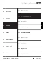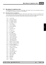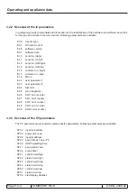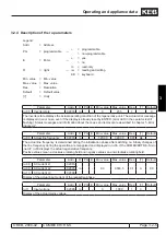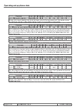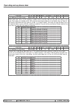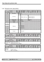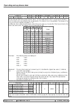
Parameter overview
© KEB, 2008-02
COMBIVERT R6-S
Page 3.1 - 5
3
10
Parameter
Addr.
R
P
E
Lower limit
Upper limit
Default
Step Unity Reference
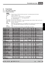
Pn.00 auto retry UP
0400h
rw
np ---
0: off
1: on
1: on
1
--- 3.6-9, 3.7-3
Pn.02 auto retry OC
0402h
rw
np ---
0: off
1: on
0: off
1
--- 3.6-9
Pn.03 E.EF stopping mode
0403h
rw
np ---
0
6
0
1
--- 3.6-6, 3.6-7, 3.6-8, 3.6-9
Pn.04 ext. fault input select
0404h
rw
np E
0
4095
64
1
--- 3.4-9, 3.6-5
Pn.05 E.bus stopping mode
0405h
rw
np ---
0
6
6
1
--- 3.6-3, 3.6-6, 3.6-7, 3.6-8,
3.6-9
Pn.06 watchdog time
0406h
rw
np E
0,00: off
60,00
0,00: off
0,01
s
3.6-6
Pn.08 warning OL stop mode
0408h
rw
np ---
0
6
6
1
--- 3.4-13, 3.6-5, 3.6-8, 3.6-9
Pn.09 OL warning level
0409h
rw
np ---
0
100
80
1
%
3.4-13, 3.6-5, 3.6-10
Pn.10 warning OH stop mode
040Ah
rw
np ---
0
6
6
1
--- 3.4-13, 3.6-3, 3.6-5, 3.6-8,
3.6-9
Pn.11 OH warning level
040Bh
rw
np ---
0
variable
70
1
Grad 3.4-13, 3.6-3, 3.6-5, 3.6-9
Pn.12 warning dOH stop. mode
040Ch
rw
np ---
0
7
7
1
--- 3.6-8, 3.6-9
Pn.14 disconnecting time E.nEt
040Eh
rw
np ---
0,00
10,00
0,00
0,01
s
3.6-8, 3.6-9, 5.1-3
Pn.15 automatic fault reset
040Fh
rw
np ---
0
10
3
1
--- 3.6-2, 3.6-9
Pn.16 warning OHI stop. mode
0410h
rw
np ---
0
6
0
1
--- 3.6-5, 3.6-8, 3.6-9, 3.6-9
Pn.17 E.OHI delay time
0411h
rw
np ---
0
300
0
1
s
3.6-5
Pn.18 E.Set stopping mode
0412h
rw
np ---
0
6
0
1
--- 3.6-6, 3.6-7, 3.6-8, 3.7-9
Pn.19 operating mode
0413h
rw
np E
0
3
0
1
--- 3.4-3, 3.5-3, 3.6-10, 4.2-3,
4.2-4, 4.2-5
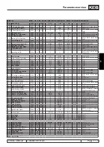
ru.00 inverter state
0200h
ro
np ---
0
255
0
1
--- 3.2-5, 3.6-3
ru.03 actual frequency display
0203h
ro
np ---
-320,00
320,00
0,00
0,01
Hz 3.2-5, 3.3-3, 3.3-4, 3.9-6,
4.2-4
ru.08 AC current L1
0208h
ro
np ---
0,0
6553,5
0,0
0,1
A
3.2-5
ru.09 AC current L2
0209h
ro
np ---
0,0
6553,5
0,0
0,1
A
3.2-5
ru.10 AC current L3
020Ah
ro
np ---
0,0
6553,5
0,0
0,1
A
3.2-5
ru.11 input voltage
020Bh
ro
np ---
0
1000
0
1
V
3.2-5
ru.13 actual utilization
020Dh
ro
np ---
0
255
0
1
%
3.2-6
ru.14 peak utilization
020Eh
rw
np ---
0
255
0
1
%
3.2-6
ru.15 DC current
020Fh
ro
np ---
0,0
6553,5
0
0,1
A
3.2-6, 3.3-3, 3.3-4
ru.16 DC current / peak value
0210h
rw
np ---
0,0
6553,5
0
0,1
A
3.2-6
ru.17 AC input current
0211h
ro
np ---
-3276,7
3276,7
0
0,1
A
3.2-6, 3.3-3, 3.3-4
ru.18 DC voltage/ reference value 0212h
ro
np ---
0
1000
0
1
V
3.2-6, 3.3-3, 3.3-4, 3.5-4,
4.2-4
ru.19 DC output voltage
0213h
ro
np ---
0
1000
0
1
V
3.2-6, 3.2-7
ru.20 peak DC voltage
0214h
rw
np ---
0
778
0
1
V
3.2-7
ru.21 input terminal state
0215h
ro
np ---
0
4095
0
1
--- 3.2-7, 3.4-3, 3.4-5
ru.22 internal input state
0216h
ro
np ---
0
4095
0
1
--- 3.2-7, 3.2-18, 3.4-3, 3.4-5,
3.4-14
ru.23 output condition state
0217h
ro
np ---
0
255
0
1
--- 3.2-8, 3.4-11, 3.4-12
ru.24
state of output flags
0218h
ro
np ---
0
255
0
1
--- 3.2-8, 3.4-11, 3.4-12
ru.25 output terminal state
0219h
ro
np ---
0
255
0
1
--- 3.2-9,
3.2-18,
3.4-11,
3.4-12, 3.4-18, 7.1-4
ru.26 active parameter set
021Ah
ro
np ---
0
7
0
1
--- 3.2-9
ru.33 ANOUT1 pre ampl. disp.
0221h
ro
np ---
-400,0
400,0
0
0,1
%
3.2-9, 3.3-4
ru.34 ANOUT1 post ampl. disp.
0222h
ro
np ---
-100,0
100,0
0
0,1
%
3.2-9, 3.3-4, 3.4-14
ru.38 power module temperature 0226h
ro
np ---
0
100
0
1
Grad 3.2-9, 3.3-3, 3.3-4, 3.4-13
ru.39 OL counter display
0227h
ro
np ---
0
100
0
1
%
3.2-10, 3.4-13, 3.6-5
ru.40 power on counter
0228h
rw
np ---
0
65535
0
1
h
3.2-10, 3.7-3
ru.41 modulation on counter
0229h
rw
np ---
0
65535
0
1
h
3.2-10
ru.43 timer 1 display
022Bh
rw
np ---
0
655,35
0
0,01
--- 3.2-10, 3.4-13, 3.8-3, 3.8-5
ru.44 timer 2 display
022Ch
rw
np ---
0
655,35
0
0,01
--- 3.2-10, 3.4-13, 3.8-3, 3.8-5
ru.46 ext. temperature
022Eh
ro
np ---
0
255
0
1
--- 3.2-10
ru.68 rated DC voltage
0244h
ro
np ---
0
1000
0
1
V
3.2-10
ru.80 digital output state
0250h
ro
np ---
0
255
0
1
--- 3.2-11, 3.2-17, 3.4-11,
3.4-12, 3.4-18
ru.81 active power
0251h
ro
np ---
-3200,00
3200,00
0,00
0,01
kW 3.2-11, 3.3-3, 3.3-4, 3.4-14,
4.2-4, 4.2-5
ru.82 total regen
0252h
rw
np ---
0
2147483647
0
1
kWh 3.2-11
ru.83 total motor
0253h
rw
np ---
0
2147483647
0
1
kWh 3.2-11
ru.84 total net
0254h
rw
np ---
0
2147483647
0
1
kWh 3.2-11
ru.85 actual net
0255h
ro
np ---
0,00
655,35
0
0,01
kVA 3.2-11
SY.02
inverter identifier
0002h
cp-ro np ---
identifier
identifier
identifier
1
hex 3.2-16, 3.7-3
SY.03 power unit code
0003h
cp-ro np E
0
32767
0
1
--- 3.2-16, 3.6-7, 5.1-5
SY.06 inverter address
0006h
rw
np E
0
239
1
1
--- 3.2-16, 7.1-4
SY.07 baud Rate ext. bus / PC
0007h
rw
np E
0
6
3
1
--- 3.2-16
SY.09 HSP5 watchdog time
0009h
cp-ro np E
0,00: off
10,00
0,00: off
0,01
s
3.2-16, 3.6-6
SY.11 baud rate int. bus
000Bh
cp-ro np E
0
10
5
1
--- 3.2-17
SY.32 scope timer
0020h
ro
np ---
0
65535
0
1
--- 3.2-17
SY.41 control word (high)
0029h
rw
np E
0
65535
0
1
hex 3.2-17, 3.2-18
SY.42 status word (high)
002Ah
ro
np ---
0
65535
0
1
hex 3.2-17, 3.2-18, 3.2-19
further on next side
Summary of Contents for combivert R6-S
Page 1: ...APPLICATION MANUAL Mat No Rev 00R6SEA K130 1 A GB KEB COMBIVERT R6 S Version 1 3 ...
Page 2: ...Page 1 1 2 COMBIVERT R6 S KEB 2008 02 Introduction ...
Page 4: ...Page 1 1 4 COMBIVERT R6 S KEB 2008 02 Introduction ...
Page 14: ...Page 1 2 6 COMBIVERT R6 S KEB 2008 02 Product overview ...
Page 28: ...Page 2 1 6 COMBIVERT R6 S KEB 2008 02 Fundamentals ...
Page 34: ...Page 2 2 6 COMBIVERT R6 S KEB 2008 02 Password structure ...
Page 116: ...Page 3 8 2 COMBIVERT R6 S KEB 2008 02 Special functions 3 8 1 Program timer counter 3 8 3 ...
Page 130: ...Page 3 9 10 COMBIVERT R6 S KEB 2008 02 Define CP Parameters ...
Page 140: ...Page4 2 2 COMBIVERT R6 S KEB 2008 02 Start up ...
Page 144: ...Page4 2 6 COMBIVERT R6 S KEB 2008 02 Start up ...
Page 150: ...Page 5 1 6 COMBIVERT R6 S KEB 2008 02 Error assistance ...
Page 158: ...Page 6 1 8 COMBIVERT R6 S KEB 2008 02 Project design ...
Page 160: ...Seite 7 1 2 COMBIVERT R6 S KEB 2008 02 Annex 7 1 1 Keyword index 7 1 3 ...
Page 166: ......
Page 167: ......


