Seite 3.4 - 6
COMBIVERT R6-S
© KEB, 2008-02
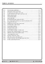
Digital in- and outputs
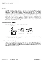
3.4.5 Digital noise filter (di.03)
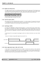
The digital noise filter reduces the sensitivity against disturbances at the digital inputs. Only hardware inputs
can be filtered. Each input has a separate filter counter, which counts upward at active input and downward at
inactive input. The output of the filter is set on reaching the filter time and reset when
reaching zero.
Parameter
Setting range
Resolution
di.03
0...127 ms
1 ms
Priority of the filter times: the higher time is used.
3.4.6 Invert the inputs (di.04)
With parameter di.04 can be adjusted whether a signal is 1- or 0- active (inverted). The parameter is bit-coded,
i.e. the appropriate value of the input must be entered. If several inputs shall be inverted, the sum is to be for-
med (Exception: inverting of the control release remains without function).
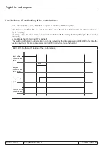
3.4.7 Input trigger (di.05)
As standard the COMBIVERT is controlled with static signals i.e., an input is set as long as a signal is active.
But in practice it may happen that a signal is only available temporary, but the input shall remain set. For this
case this or several inputs can be set to input trigger. A rising slope with a pulse duration, which is longer than
the response time of the digital filter
is
sufficient for switching on. Switching off is done with the next rising slo
-
pe.
Control release (ST) can be adjusted to input trigger, but this has no effect to the function, since this is a static
signal.
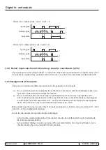
Picture 3.4.7 Example of a signal flow diagram for input (
di.05 = 16)
Slope-triggering
t
t
Input trigger
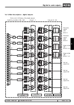
3.4.8 Strobe-dependent inputs (di.06, di.07, di.08)
A strobe signal is mainly used for triggering the input signals. For example, two inputs are used for parameter
set selection. The incoming signals to the control are not simultaneously, so that it would be switched into an
unwanted set for a short-time. For active strobe (scanning signal) the actual input signals of the strobe-depen-
dent inputs are stored and have been retained to the next scanning.
Summary of Contents for combivert R6-S
Page 1: ...APPLICATION MANUAL Mat No Rev 00R6SEA K130 1 A GB KEB COMBIVERT R6 S Version 1 3 ...
Page 2: ...Page 1 1 2 COMBIVERT R6 S KEB 2008 02 Introduction ...
Page 4: ...Page 1 1 4 COMBIVERT R6 S KEB 2008 02 Introduction ...
Page 14: ...Page 1 2 6 COMBIVERT R6 S KEB 2008 02 Product overview ...
Page 28: ...Page 2 1 6 COMBIVERT R6 S KEB 2008 02 Fundamentals ...
Page 34: ...Page 2 2 6 COMBIVERT R6 S KEB 2008 02 Password structure ...
Page 116: ...Page 3 8 2 COMBIVERT R6 S KEB 2008 02 Special functions 3 8 1 Program timer counter 3 8 3 ...
Page 130: ...Page 3 9 10 COMBIVERT R6 S KEB 2008 02 Define CP Parameters ...
Page 140: ...Page4 2 2 COMBIVERT R6 S KEB 2008 02 Start up ...
Page 144: ...Page4 2 6 COMBIVERT R6 S KEB 2008 02 Start up ...
Page 150: ...Page 5 1 6 COMBIVERT R6 S KEB 2008 02 Error assistance ...
Page 158: ...Page 6 1 8 COMBIVERT R6 S KEB 2008 02 Project design ...
Page 160: ...Seite 7 1 2 COMBIVERT R6 S KEB 2008 02 Annex 7 1 1 Keyword index 7 1 3 ...
Page 166: ......
Page 167: ......

