GB - 13
Control
2.5
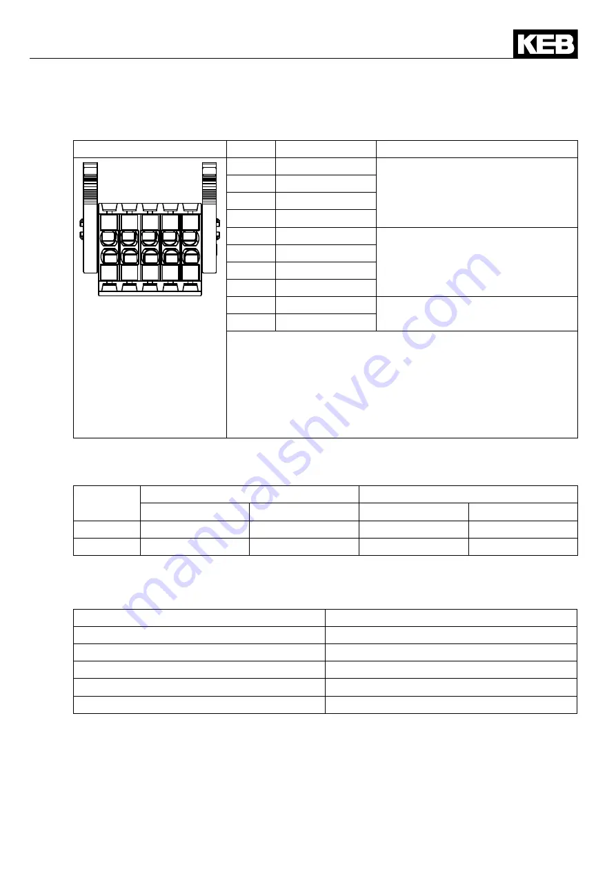
Assignment of the STO terminal strip X2B
X2B
PIN
Name
I/O
1
2
3 5
6
7
8
9
10
4
1
STO1+
Input STO channel 1
2
STO1+
3
STO1-
4
STO1-
5
STO2+
Input STO channel 2
6
STO2+
7
STO2-
8
STO2-
9
STO-OUT
Output STO
10
STO-OUT
The individual channels are designed potential-free, so 24V
and 0 V can be connected. The inputs are designed by way that
safety switchgear units with test pulses (OSSD signals) can be
connected. The signals are not evaluated, they are only filtered.
The OSSD test interval is limited to 10 ms.
The reference potential for output STO-OUT (terminals X2B/9
and 10) is the mass of the control 0V (terminal X2A/26).
2.5.1 Inputs
2.5.1.1
Specification of the STO inputs
STO
Inputs
Status 0
Status 1
UL [V]
IL [mA]
UH [V]
IH [mA]
max.
5
25
30
25
min.
-3
not defined
15
5
The maximum short-term starting current of the input is limited to 300 mA.
2.5.1.2
STO with OSSD signals
The filter time depends on the minimum input voltage and can be specified as follows:
Input voltage [V]
OSSD pulse width [ms]
15
0.1
18
0.8
20
1.1
24
1.5
30
1.8
2.5.2 Output STO
The short-circuit proof, digital output is specified in accordance with IEC61131-2. The output
rated current is 100 mA at 24 Vdc. The output is 24 Vdc if the inputs STO1 and STO2 are set.
Summary of Contents for COMBIVERT S6 Series
Page 2: ......
Page 32: ...GB 31 Notices...


