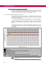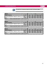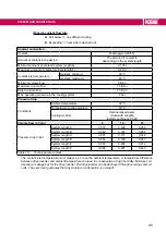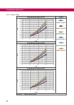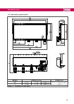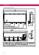
3.2 System and module data
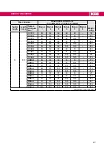
3.2.1 System weight
.
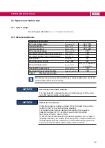
3.2.2 Electrical system data
Electrical system data
DC input voltage range
U
in_HV_dc
/ V
520…750
Limited operation 1
U
HV1_dc
/ V
200…520
Limited operation 2
U
HV2_dc
/ V
750…820
DC rated input voltage
U
N_HV_dc
/ V
565
DC switch-off level „Error! Underpotential“
U
UP_dc
/ V
180
DC switch-off level „Error! Overpotential“
U
OP_dc
/ V
820
Rated power
P
N
/ kW
60
Maximum power for 60s
P
_max
/ kW
90
DC rated input current
I
in_HV_dc
/ A
Σ I
in_HV_dc_drive modules
<
I
_max_HV_dc
Nominal DC input current
I
N_HV_dc
/ A
120
Maximum DC input current for 60s
I
_max_HV_dc
/ A
180
Table 8:
Electrical system data
The DC rated input current at the HV DC input corresponds to the sum of the
currents of the active drive modules.
NOTICE
Destruction of the drive modules
The individual drive modules must be controlled by way that the maxi-
mum DC input current is not exceeded.
NOTICE
Defect due to overload
Protective measures against overload of the HV supply lines and pro-
tection for the T6
APD
system shall be provided.
The following fuse has been tested to protect the T6
APD
system:
SIBA Part number: 20 713 32.280 (Type aR 900 V DC / 280 A)
Test mains: 750 V DC, SCCR: 30 kA.
To ensure the effectiveness of the protective measures in error case, it
is always necessary to consider the entire system in order to determine
the appropriate protective measures. Incorrect dimensioning does not
ensure the correct response time of the protective devices.
37
SYSTEM AND MODULE DATA
Summary of Contents for COMBIVERT T6APD
Page 2: ......

