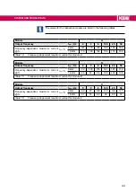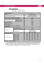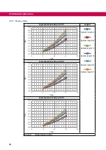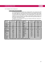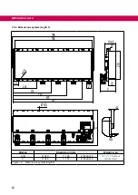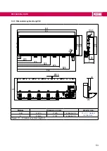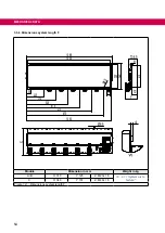
Operation in the range of the thermal overload limit
Due to the high steepness of the overload characteristic, the duration of a permissible
overload in this range cannot be determined exactly. Therefore, the design of the drive
inverter should be assumed to have a maximum overload time of 300s.
3.2.5.2 Frequency-dependent maximum current (OL2)
The characteristics of the maximum currents for a switching frequency which are de-
pending on the output frequency are different for each
drive inverter, but the following
rules are generally applicable:
• Lower maximum currents apply for switching frequencies > rated switching frequency.
If error (OL2) shall be triggered on exceeding the maximum currents or if the switching
frequency is automatically reduced (derating) can be adjusted in the drive inverter pa-
rameters.
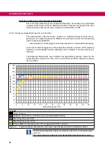
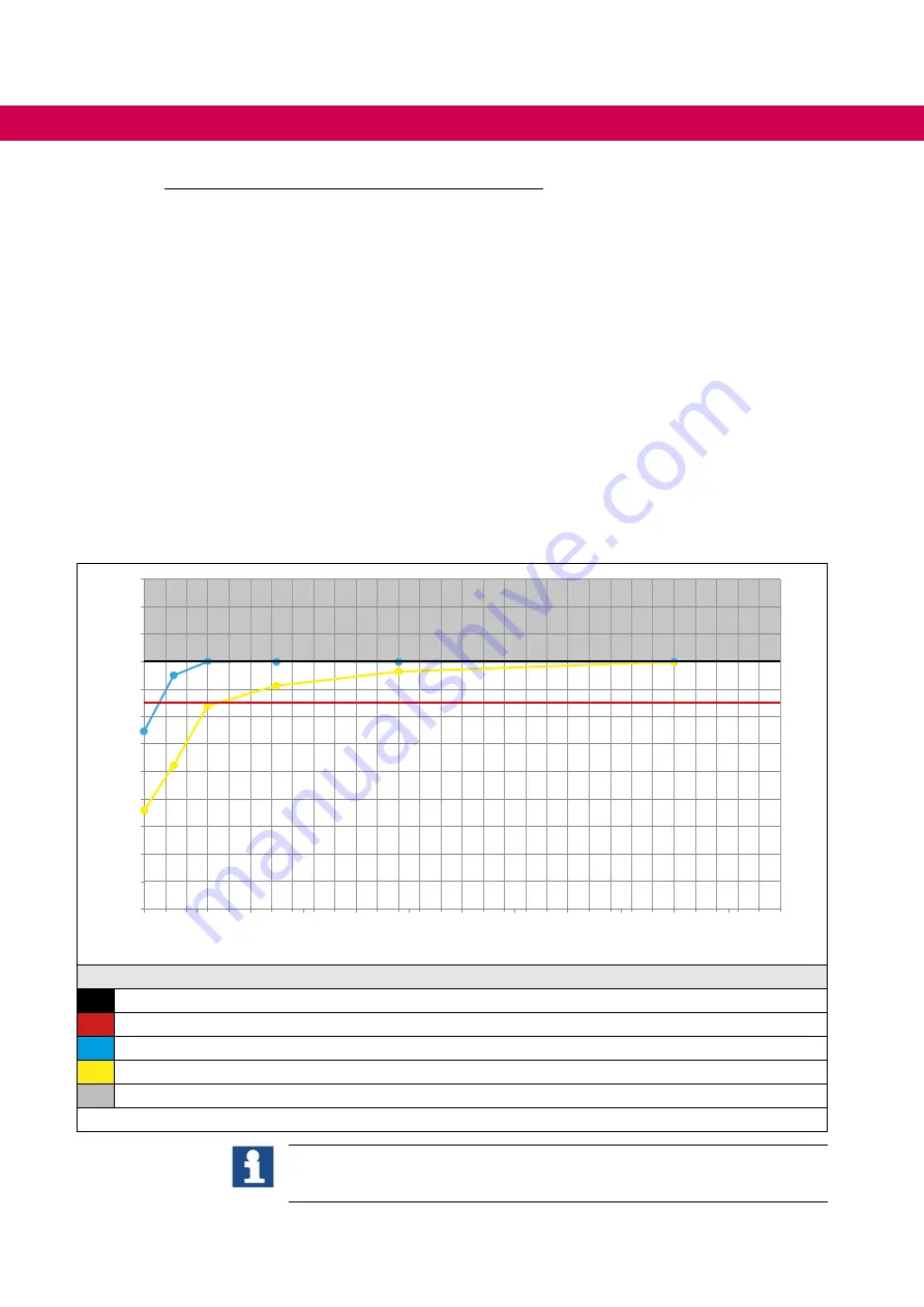
The following characteristic curve indicates the permissible maximum current for the
output frequency values 0 Hz, 3 Hz, 6 Hz, 12,5 Hz 25 Hz and 50 Hz. Module A is shown
as an example.
0
20
40
60
80
100
120
140
160
180
200
220
240
0
5
10
15
20
25
30
35
40
45
50
55
60
Output frequency in Hz
Maximum current in %
Legend
Overcurrent
I
OC
Software current limit
I
lim
(the limit can be set with parameter is35)
Switching frequency 8 kHz
Switching frequency 16 kHz
Not available for modulation. Error OC is triggered at 180% overload.
Figure 7:
Typical overload characteristic in the lower output frequencies (OL2) Example module A
The frequency-dependent maximum current
I
lim
refers in % to the rated output
current
I
N
.
The current remains constant from the last specified output frequency value.
42
SYSTEM AND MODULE DATA
Summary of Contents for COMBIVERT T6APD
Page 2: ......


