background image

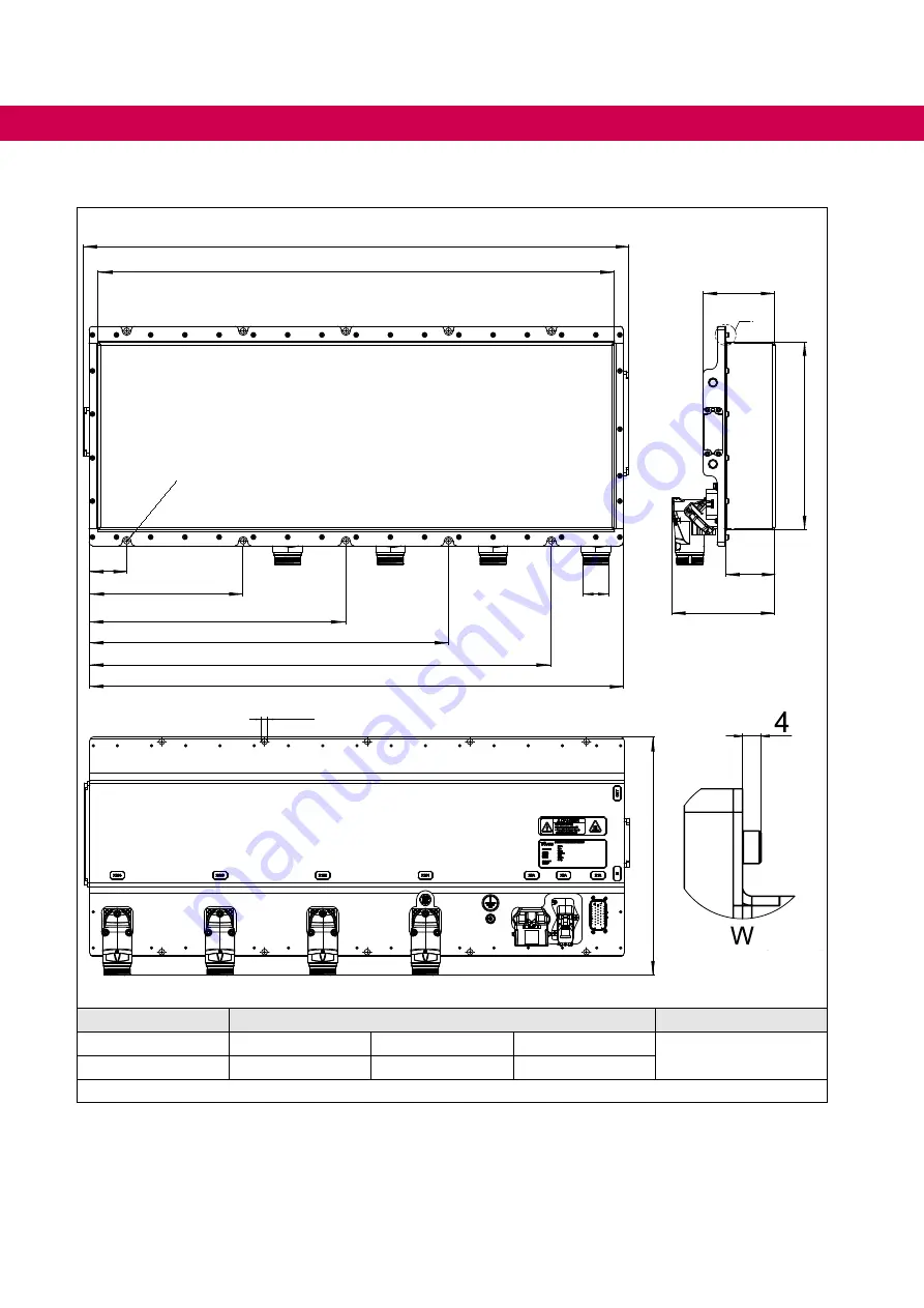
3.3.4  Dimensions system length D

55

225

375

525

675

780

754

796

R6,6

Z

104,5

274

72

Y

W

Ø8,5

X

Module

Dimension in mm

Weight in kg

A / B

X: 310

Y: 125

Z:  M23 x 1.5

=> 

„2.1.1 System 

architecture“

C

X: 348

Y: 151

Z:  M40 x 1.5

Figure 12:  Dimensions system length D

52

 MECHANICAL  DATA

Summary of Contents for COMBIVERT T6APD

Page 1: ...COMBIVERT T6APD INSTRUCTIONS FOR USE INSTALLATION MODULAR DRIVE CONVERTER SYSTEM Translation of the original manual Document 20108384 EN 05 ...

Page 2: ......

Page 3: ... the following warning signs DANGER Dangerous situation which will cause death or serious injury iif this safe ty warning is ignored WARNING Dangerous situation which may cause death or serious injury if this safety warning is ignored CAUTION Dangerous situation which may cause minor injury if this safety warning is ignored NOTICE Situation which can cause damage to property if this safety warning...

Page 4: ...dvice in spoken and written and through tests are made to best of our knowledge and information about the intended use However they are regarded as being only informal and changes are expressly reserved in particular due to technical changes This also applies to any violation of industrial property rights of a third party Selection of our units in view of their suitability for the intended use mus...

Page 5: ...use 15 1 3 Installation 16 1 4 Electrical connection 17 1 4 1 EMC compatible installation 18 1 4 2 Voltage test 18 1 4 3 Insulation measurement 18 1 5 Requirements to the entire system 18 1 6 Start up and operation 19 1 7 Maintenance 21 1 8 Repair 21 1 9 Disposal 22 2 Product Description 23 2 1 T6APD Principle construction 25 2 1 1 System architecture 26 2 2 Specified application 29 2 2 1 Residual...

Page 6: ...ture 44 3 2 7 Cooling and coolant connection 44 3 2 7 1 Pressure drops 46 3 2 7 2 Materials in the cooling circuit 47 3 2 8 Requirements for the coolant 48 3 3 Mechanical data 49 3 3 1 Dimensions system length A 49 3 3 2 Dimensions system length B 50 3 3 3 Dimensions system length C 51 3 3 4 Dimensions system length D 52 3 3 5 Dimensions system length E 53 3 3 6 Dimensions system length F 54 3 3 7...

Page 7: ... 3 3 3 Connection of the temperature input in operating mode PTC 71 4 4 Connection of the control 72 4 4 1 Assignment of the connector X1A 72 4 4 1 1 Terminal 15 Enable 74 4 4 1 2 Specification of the CAN bus 74 4 4 1 3 Connection example 1 Connection of the CAN client at T6APD 75 4 4 1 4 Connection example 2 Assignment of both CAN interfaces with T6APD at the end of the respective bus 76 4 4 2 Co...

Page 8: ...tic fields 59 Figure 20 Connection at DC voltage supply 60 Figure 21 Example of a HVIL wiring 61 Figure 22 Protective earth 61 Figure 23 HV DC supply X3A front view on the device 62 Figure 24 Coupling for HV DC supply counterpart for X3A 63 Figure 25 Wiring between motor and T6APD 64 Figure 26 Socket inverter module A and B front view socket 65 Figure 27 Coupling motor connector for inverter modul...

Page 9: ... 15 Frequency dependent maximum current for module B 43 Table 16 Frequency dependent maximum current for module C 43 Table 17 Switching frequency and temperature 44 Table 18 Technical data coolant 45 Table 19 Electrochemical series standard potentials against hydrogen 47 Table 20 General requirements for the coolant 48 Table 21 Plug in connector coding 63 Table 22 Possible applications of temperat...

Page 10: ...es DS 402 CiA DS 402 CAN device profile for drives ECE regulati ons ECE regulations describe a catalog of internationally agreed uniform technical regulations for vehicles parts and equipment of motor vehic les EMC Electromagnetic compatibility Emergency stop Shutdown of a drive in emergency case not de energized Emergency switching off Switching off the voltage supply in emergency case EN Europea...

Page 11: ...s are controlled NN Sea level PE Protective earth PELV Protective Extra Low Voltage PLC Programmable Logic Controller PLC Programmable logic controller Power on De mand Auxiliary units are only activated when required the T6 system ensures a suitable and efficient adaptation of voltage currents and frequencies PT1000 Temperature sensor with R0 1000Ω PTC PTC resistor for temperature detec tion PWM ...

Page 12: ...ental testing Part 2 38 Tests Test Z AD Composite temperature humidity cyclic test IEC 60068 2 38 German version EN 60068 2 38 DIN EN 60068 2 52 Environmental testing Part 2 Tests Test Kb Salt mist cyclic sodium chloride solution IEC 60068 2 52 German version EN 60068 2 52 DIN EN 60068 2 64 Environmental testing Part 2 64 Tests Test Fh Vibration broadband random and guidance IEC 60068 2 64 German ...

Page 13: ...rbances from narrowband radiated electromagnetic energy Part 4 Harness excitation methods ISO 11783 1 Tractors and machinery for agriculture and forestry Serial control and commu nications data network Part 1 General standard for mobile data communication ISO 16750 1 Road vehicles Environmental conditions and testing for electrical and elect ronic equipment Part 1 General ISO 16750 2 Road vehicles...

Page 14: ...g systems Vo 2015 208 Commission delegated regulation EU 2015 208 of 8 December 2014 supple menting Regulation EU No 167 2013 of the European Parliament and of the Council with regard to vehicle functional safety requirements for the approval of agricultural and forestry vehicles ...

Page 15: ...get group This instruction manual is determined exclusively for electrical personnel Electrical per sonnel for the purpose of this instruction manual must have the following qualifications Knowledge and understanding of the safety instructions Skills for installation and assembly Start up and operation of the product Understanding of the function in the used machine Detection of hazards and risks ...

Page 16: ...he drive inverter must not be opened The device must not be put into operation in case of mechanical defects Non com pliance with the applicable standards Mount the drive inverter according to the specified degree of protection Position protected as possible against environmental influences and mechanical environ mental conditions Note installation position and minimum distances to surrounding ele...

Page 17: ...y side of this product Drive inverters with a leakage current 3 5mA AC current 10mA DC current are intended for a stationary connection Protective earth conductors must be designed in accordance with the local reg ulations for equipment with high leakage currents according to DIN EN 61800 5 1 EN 60204 1 or DIN IEC 60364 5 54 For a trouble free and safe operation please pay attention to the followi...

Page 18: ...er unit connections grid connected potential and all control connections are bridged with PE 1 5 Requirements to the entire system To ensure the electrical safety of the entire system the following must be observed in accordance with the requirements of ISO 6469 3 The HV DC AC circuits must be provided with protective separation or increased insulation compared to the touchable LV circuits The ins...

Page 19: ...ntrol unit where the customer can store software related to his application customer software The customer software can already be installed at KEB on request NOTICE Use of customer software in our devices The use of customer software in the target products with regard to location purpose and application is outside our control and there fore lies exclusivelsy in the area of responsibility of the c...

Page 20: ...e maintained when connected Use only approved accessories for this device Never touch terminals or cable ends Switching at the output Switching between motor and drive inverter is prohibited for single drives during oper ation as this may trigger the protection gear of the device Function speed search must be activated if switching can not be avoided Control release may only be triggered after clo...

Page 21: ...oises or smells inform a person in charge DANGER Unauthorized exchange repair and modifications Unpredictable malfunctions The function of the drive inverter is dependent on its parameteriza tion Never replace drive inverter without knowledge of the applica tion Modification or repair is permitted only by authorized personnel by KEB Only use original manufacturer parts Infringement will annul the ...

Page 22: ...rom the list below Shipping costs are paid by the customer Thereupon the devices will be professionally recycled and disposed The entry numbers are listed country specific in the following table The corresponding KEB return addresses can be found on our website Withdrawal by WEEE Reg No Keyword Austria KEB Automation GmbH ERA 51976 Stichwort Rücknahme WEEE France RÉCYLUM Recycle point ADEME FR0218...

Page 23: ... control of each inverter supports a great number of control algorithms Sup ported motor types are synchronous and asynchronous motors and synchronous reluc tance motors T6APD enables dynamic energy efficient speed and torque control and closed loop po sitioning without the need of encoder feedback SCL sensorless closed loop Intelligent control and variable communication connection The intelligent...

Page 24: ...control of motors Automatic identification of motor resistance inductance and rotor position detection EMC Electromagnetic compatibility Integrated common mode DC EMC filters in each inverter module for decoupling from the high voltage DC voltage supply Applications Electrification of auxiliary units and auxiliary drives Power steering pumps air compressors air conditioning and cooling systems tur...

Page 25: ...egend HV DC High voltage DC supply LV DC Low voltage DC supply CAN bus Communication MCU Main Control Unit Central connection unit intelligent control PLC and switch mode power supply SNT Filter DC EMC filter M1 Mn Inverter modules A B C Figure 1 T6APD Principle construction 25 Product Description ...

Page 26: ... 13 5 BA 33 16 5 13 4 AA 16 5 16 5 13 3 C 646 CCC 60 60 60 19 8 CCB 60 60 33 19 2 CCA 60 60 16 5 19 1 CBB 60 33 33 18 5 CBA 60 33 16 5 18 4 CAA 60 16 5 16 5 18 3 BBB 33 33 33 17 9 BBA 33 33 16 5 17 8 BAA 33 16 5 16 5 17 7 AAA 16 5 16 5 16 5 17 6 D 796 CCCC 60 60 60 60 25 CCCB 60 60 60 33 24 3 CCCA 60 60 60 16 5 24 2 CCBB 60 60 33 33 23 7 CCBA 60 60 33 16 5 23 6 CCAA 60 60 16 5 16 5 23 5 CBBB 60 33...

Page 27: ...CCAA 60 60 60 16 5 16 5 28 6 CCBBB 60 60 33 33 33 28 2 CCBBA 60 60 33 33 16 5 28 1 CCBAA 60 60 33 16 5 16 5 28 CCAAA 60 60 16 5 16 5 16 5 27 9 CBBBB 60 33 33 33 33 27 6 CBBBA 60 33 33 33 16 5 27 5 CBBAA 60 33 33 16 5 16 5 27 4 CBAAA 60 33 16 5 16 5 16 5 27 3 CAAAA 60 16 5 16 5 16 5 16 5 27 2 BBBBB 33 33 33 33 33 27 BBBBA 33 33 33 33 16 5 26 9 BBBAA 33 33 33 16 5 16 5 26 8 BBAAA 33 33 16 5 16 5 16 ...

Page 28: ... 16 5 32 6 CCBBAA 60 60 33 33 16 5 16 5 32 5 CCBAAA 60 60 33 16 5 16 5 16 5 32 4 CCAAAA 60 60 16 5 16 5 16 5 16 5 32 3 CBBBBB 60 33 33 33 33 33 32 1 CBBBBA 60 33 33 33 33 16 5 32 CBBBAA 60 33 33 33 16 5 16 5 31 9 CBBAAA 60 33 33 16 5 16 5 16 5 31 8 CBAAAA 60 33 16 5 16 5 16 5 16 5 31 7 CAAAAA 60 16 5 16 5 16 5 16 5 16 5 31 6 BBBBBB 33 33 33 33 33 33 31 5 BBBBBA 33 33 33 33 33 16 5 31 4 BBBBAA 33 3...

Page 29: ...800 5 1 for inverter modules is used The harmonized standards DIN EN 61800 3and DIN EN 61800 5 1 were used The machine directive EMC directive Low Voltage Directive ECE R10 Rev 5 ECE R100 Rev 2 and other guidelines and regulations must be observed depending on the version Technical data and information for connection conditions shall be taken from the name plate and from the instruction manual and...

Page 30: ... the loss of all claims against the manufacturer 2 4 Overview of the COMBIVERT T6APD X3A X1A X2A X1B2 max X1B6 X1B1 IN OUT Legend 1 Nameplate 2 Central ground connection connection for protective earth 4 3 1 2 Protective earth 3 Pressure compensation valve for the housing X1A Connector for control signals LV DC input electrical system HVIL CAN and KEB diagnosis X2A Ethernet interface RJ45 X3A HV D...

Page 31: ...K9K Modul X1B1 16 5A 10 R 05 8958 Legend 1 Barcode with serial number 2 Test mark CE or E1 3 Serial number order number Year and week of manufacture Factory 4 Material number basic unit 2 7 Type code version number 5 Options 2 6 Configurable options 6 Technical data Input 7 Technical data Output 8 Number and maximum current of the integrated modules 9 Manufacturer identification 10 QR code for fur...

Page 32: ...tility With e g J1939 Gateway power steering pump air compressor etc APP Pool FTxx Object licenses to activate the individual T6 App s MCU Files Pxxx Download files e g application specific parameter lists and system configuration ID DCU Firmware SWDxxx DCU Firmware Release Output frequency LIM Limitation to 599 Hz export restriction ULO Output frequencies up to 2000 Hz Warranty WSTD Warranty stan...

Page 33: ...tem length A 346mm B 496mm C 649mm D 796mm E 946mm F 1096mm Reserved 0 Default value Control type A KEB default Series T6 COMBIVERT T6APD System 00 System 0 default Table 3 Type code The type code is not used as order code but only for identification 33 Product Description ...

Page 34: ... Site altitude Max 2000m above sea level Table 4 Evironmental conditions 3 1 2 Mechanical environmental conditions Storage Standard Class Notes Vibration limits ISO 16750 3 Code L Commercial vehicles sprung mass Frequency 10 2000Hz acceleration 57 9m s2 Shock limit values ISO 16750 3 Code L Shock 6ms acceleration 500m s2 Transport Standard Class Notes Vibration limits ISO 16750 3 Code L Commercial...

Page 35: ...ation 2 5kV Basic insulation between HV DC AC and PE housing DC test voltage 2260V 60s Pulse voltage Protective separation 4kV Protective separation or rein forced insulation between HV DC AC and LV DC DC test voltage 4240V 60s Energy HV DC to PE ISO 6469 3 0 2J AC touch current 5mA Pollution degree For environmental conditions 3 1 1 Evironmental condi tions Table 6 Device classification 35 Operat...

Page 36: ...Interference Immunity Standard Level Notes Electromagnetic fields ECE R10 Rev 5 Vo 2015 208 DIN EN 61000 4 3 10V m 3V m 1V m 80MHz 1GHz 1 4 2GHz 2 2 7GHz Cable fed disturbances ECE R10 Rev 5 Vo 2015 208 Static discharges DIN EN 61000 4 2 8kV 4kV AD air discharge CD contact discharge Burst Ports for process meas urement control lines and signal interfaces DIN EN 61000 4 4 1kV Burst Power supply int...

Page 37: ...system data The DC rated input current at the HV DC input corresponds to the sum of the currents of the active drive modules NOTICE Destruction of the drive modules The individual drive modules must be controlled by way that the maxi mum DC input current is not exceeded NOTICE Defect due to overload Protective measures against overload of the HV supply lines and pro tection for the T6APD system sh...

Page 38: ...igure 4 AIC with 7 2 Uk choke filtering Figure 5 AIC with sine wave EMC filter The COMBIVERT T6APD is equipped with DC HF filters in the DC link When operating an AIC in DC bus connection with the COMBIVERT T6APD the AIC must be operated with a sine wave EMC filter No switching frequency depending voltage between DC link to earth and DC link to earth may occur This is shown as example in Figure 4 ...

Page 39: ...s prescribed by an external fuse supplied by the customer The design of the fuse is in the responsibility of the customer The T6APD system must be protected with a maximum fuse value of 15 A It is recom mended to use a flat vehicle fuse type Mini or standard The voltage range of the following table must be obtained at the system input at the connector Starting current note The internal electrolyti...

Page 40: ...cy 3 fS_max kHz 16 Overload current over time IOL 3 2 5 1 Overload characteristic OL Maximum current If0 Ifd 3 2 5 2 Frequency dependent maximum current OL2 Power dissipation at rated operation 4 PD W 239 462 808 Table 13 Electrical data of the inverter modules 1 The protection functions are designed for rated operation with 8 kHz 2 The output frequency is to be limited in such a way that it does ...

Page 41: ...ependent maximum current can be exceeded before and error OL2 can be triggered 3 2 5 2 Frequency dependent maximum current OL2 0 30 60 90 120 150 180 210 240 270 300 110 120 130 140 150 160 170 180 400 500 Motor current drive inverter rated currrent Overload characteristic OC level 180 Release time s Legend 1 Thermal overload limit 2 Limitation by the software current limit the limit can be set wi...

Page 42: ...the switching frequency is automatically reduced derating can be adjusted in the drive inverter pa rameters The following characteristic curve indicates the permissible maximum current for the output frequency values 0Hz 3Hz 6Hz 12 5Hz 25Hz and 50Hz Module A is shown as an example 0 20 40 60 80 100 120 140 160 180 200 220 240 0 5 10 15 20 25 30 35 40 45 50 55 60 Output frequency in Hz Maximum curr...

Page 43: ...um current for module A Module B Output frequency fout Hz 0 3 6 12 5 25 50 Frequency dependent maximum current fS Ilim 8kHz 79 109 155 161 167 172 16kHz 46 67 94 100 103 106 Table 15 Frequency dependent maximum current for module B Module C Output frequency fout Hz 0 3 6 12 5 25 50 Frequency dependent maximum current fS Ilim 8kHz 60 87 103 110 112 117 16kHz 37 53 63 65 68 72 Table 16 Frequency dep...

Page 44: ...B C Rated switching frequency 1 fSN kHz 8 Minimum switching frequency 1 fS_min kHz 8 Maximum switching frequency 1 fS_max kHz 16 Maximum heat sink temperature THS C 75 80 Temperature for derating the switching frequency TDR C 65 70 Temperature for uprating the switching frequency TUR C 45 50 Temperature for switching to rated switching frequency TEM C 70 75 Maximum internal temperature TIT C 95 Ta...

Page 45: ...oling medium 30 C Cooling medium Demineralised water mixed with Longlife radiator antifreeze C 040 Volume flow in l min 5 10 15 Pressure drop in bar System length A 0 037 0 126 0 256 System length B 0 042 0 140 0 284 System length C 0 051 0 171 0 348 System length D 0 054 0 180 0 367 System length E 0 060 0 202 0 412 System length F 0 066 0 221 0 449 Table 18 Technical data coolant 1 The coolant i...

Page 46: ...m length B System length C System length D l min Typical pressure drop at 45 C bar 0 00 0 05 0 10 0 15 0 20 0 25 0 30 0 35 0 40 0 45 0 50 0 5 10 15 20 System length E System length F l min Typical pressure drop at 65 C bar 0 00 0 05 0 10 0 15 0 20 0 25 0 30 0 35 0 40 0 45 0 50 0 5 10 15 20 l min Figure 8 Typical pressure drops 46 System and module data ...

Page 47: ...s and seals take care that halogen free materials are used A liability for occuring damages by wrongly used materials and from this resulting corro sion cannot be taken over Material formed ion Standard poten tial Material formed ion Standard poten tial Lithium Li 3 04V Nickel Ni2 0 25V Potassium K 2 93V Tin Sn2 0 14V Calcium Ca2 2 87V Lead Pb3 0 13V Sodium Na 2 71V Iron Fe3 0 037V Magnesium Mg2 2...

Page 48: ...oltage difference Hard water Cooling water may not cause scale deposits or loose excre tions It shall have a low total hardness 20 d especially carbon hardness Soft water Soft water 7 dH corrodes the material Frost protection An appropriate antifreeze must be used for applications when the heat sink or the coolant is exposed temperatures below zero Use only products of the same company for a bette...

Page 49: ...em length A W 330 55 225 R 6 6 304 307 320 346 Z 72 Y 274 104 5 X Ø8 5 W 4 Module Dimension in mm Weight in kg A B X 310 Y 125 Z M23x1 5 2 1 1 System architec ture C X 348 Y 151 Z M40x1 5 Figure 9 Dimensions system length A 49 Mechanical data ...

Page 50: ...B 454 55 225 375 R 6 6 307 320 480 496 Z 274 104 5 72 Y W X Ø8 5 Module Dimension in mm Weight in kg A B X 310 Y 125 Z M23x1 5 2 1 1 System archi tecture C X 348 Y 151 Z M40x1 5 Figure 10 Dimensions system length B 50 Mechanical data ...

Page 51: ...604 55 225 375 525 630 646 320 307 R 6 6Z Y 72 274 104 5 W Ø8 5 X Module Dimension in mm Weight in kg A B X 310 Y 125 Z M23x1 5 2 1 1 System architec ture C X 348 Y 151 Z M40x1 5 Figure 11 Dimensions system length C 51 Mechanical data ...

Page 52: ...D 55 225 375 525 675 780 754 796 R 6 6 Z 104 5 274 72 Y W Ø8 5 X Module Dimension in mm Weight in kg A B X 310 Y 125 Z M23x1 5 2 1 1 System architecture C X 348 Y 151 Z M40x1 5 Figure 12 Dimensions system length D 52 Mechanical data ...

Page 53: ...25 375 525 675 825 930 904 946 R 6 6 307 320 Z 104 5 274 72 Y W Ø8 5 X Module Dimension in mm Weight in kg A B X 310 Y 125 Z M23x1 5 2 1 1 System architecture C X 348 Y 151 Z M40x1 5 Figure 13 Dimensions system length E 53 Mechanical data ...

Page 54: ...75 525 675 825 975 1080 1054 1096 R 6 6 307 320 Z 104 5 274 72 Y W X Ø8 5 Module Dimension in mm Weight in kg A B X 310 Y 125 Z M23x1 5 2 1 1 System archi tecture C X 348 Y 151 Z M40x1 5 Figure 14 Dimensions system length F 54 Mechanical data ...

Page 55: ...4 OUT Coolant outlet G1 4 Figure 15 Connection to the coolant It is recommended to connect the G1 4 internal thread together with a G1 4 exter nal thread It is necessary to seal the fitting via the external threading A suitable sealing element must be used Metallic seals should be made of the same material as the heat sink The general manufacturer specific mounting methods apply for mounting 55 Me...

Page 56: ...e general processing requirements of the paint manufacturer apply NOTICE Damage to the housing surface Only the specified fastening materials may be used All mounting holes must be used In the corner area of the housing cover heat affected edges can occur caused by the production The tightness is also guaranteed at these components Legend 1 Holes Ø 8 5mm number and position 3 3 Mechanical data Fig...

Page 57: ... NOTICE Damage to the housing cover Clamping against the housing cover is not permitted Clamping on the M4 screw heads is not permitted for push through mounting min 4mm Legend 1 Mounting wall 2 Fixing with screw and spacer 1 through the mounting wall 3 Recess in housing cover and M4 screw heads Figure 17 Push through mounting 1 The spacer is not included or available as an accessory 57 Installati...

Page 58: ...4 2 Permissible installation position The following figure shows all permissible installation positions Figure 18 Permissible installation position 58 Installation and Connection ...

Page 59: ...etic fields NOTICE Faulty current measurements External magnetic fields can negatively influence the current measure ment Do not place or lay any current carrying wires batteries electric motors switches magnets in the marked recommended restricted area 59 Installation and Connection ...

Page 60: ...interlock of the vehicle control or insulation monitor 4 Precharging circuit 5 Fuses type aR pay attention to the permissible voltage range 3 2 2 Elec trical system data 6 HV DC coupling not included in the scope of delivery 7 KEB COMBIVERT T6APD Figure 20 Connection at DC voltage supply The T6APD must be pre charged via a appropriate circuit This is to be carried out for example passively with a ...

Page 61: ...oop HVIL T6APD X3A X1A Interlock Other HVIL HV Battery HV DC Figure 21 Example of a HVIL wiring 4 3 1 2 Protective earth The protective earth PE serves for electrical safety particularly personal protection in error case The connection cable of the protective earth should be as short as possible It is recommended to use a metal powder tape Name Function Cross section Tightening torque Protective e...

Page 62: ...ww rosenberger de Name HVR 200 Coupler with HVIL Part No pin connector H2S204 02 000B1 A Coding pin connector A 3 4 1 2 Contact Name Description 1 HV DC High voltage DC input 2 HV DC High voltage DC input 3 HVIL_in Is used to open the Interlock Loop 4 HVIL_out Is used to open the Interlock Loop Figure 23 HV DC supply X3A front view on the device Suitable mating connector 4 3 1 4 Coupling for HV DC...

Page 63: ...ing connector A Tightening torque according to manufacturer s specification 4Nm 0 4Nm Preload force according to manufacturer s specification 75N 1 4 3 2 Contact Name Description 1 HV DC High voltage DC input 2 HV DC High voltage DC input 3 HVIL_in Is used to open the Interlock Loop 4 HVIL_out Is used to open the Interlock Loop Figure 24 Coupling for HV DC supply counterpart for X3A Manufacturer p...

Page 64: ...ional earth 4 Double shielding if cable for temperature monitoring is integrated in the motor cable 5 Three phase motor observe the connection instructions of the motor manufacturer 6 Temperature monitoring Figure 25 Wiring between motor and T6APD 1 A low capacitance cable must be used The maximum permissible total cable length per connection is 30m 4 3 2 5 Motor cable length 64 Connection of the ...

Page 65: ... Socket X1B 310 horizontal rotation 310 Contact Description A Not assigned B Motor connection phase U C Motor connection phase V D Motor connection phase W PE Protective earth connection 1 TA1 temperature monitoring 4 TA2 temperature monitoring 2 3 5 8 Not assigned Figure 26 Socket inverter module A and B front view socket An unlocked connector must be closed with a protective cap with IP67 IP69k ...

Page 66: ... No Pin contact motor connection 1621581 is required 4x Crimp range motor connection 2 5 mm2 4 mm2 Part No Pin contact temperature monitoring 1618458 is required 2x Crimp range temperature monitoring 0 25 mm2 1 mm2 Figure 27 Coupling motor connector for inverter module A and B 1 The interface is not waterproof in disassembled state 2 Water can be transported into the device through a capillary eff...

Page 67: ... Socket X1B 310 horizontal rotation 310 Contact Description A Not assigned B Motor connection phase U C Motor connection phase V D Motor connection phase W PE Protective earth connection 1 TA1 temperature monitoring 4 TA2 temperature monitoring 2 3 5 8 Not assigned Figure 28 Socket inverter module C front view socket An unlocked connector must be closed with a protective cap with IP67 IP69k Part N...

Page 68: ...m Part No Pin contact motor connection 1623386 is required 4x Crimp range motor connection 16 mm2 Part No Pin contact temperature monitoring 1623613 is required 2x Crimp range temperature monitoring 1 mm2 1 5 mm2 Figure 29 Coupling motor connector for inverter module C 1 The interface is not waterproof in disassembled state 2 Water can be transported into the device through a capillary effect of t...

Page 69: ...ect motor against voltage peaks Drive inverters switch at the output with high dV dt Voltage peaks that endanger the insulation system at the motor can occur espe cially in case of long motor cables 15 m NOTICE Connection of the drive in star connection The star point must not be earthed 4 3 3 Temperature detection The COMBIVERT T6APD has implemented a switchable temperature detection The in put h...

Page 70: ... Connection of a KTY sensor NOTICE Störungen durch Fehlmessungen Protection of the motor winding no longer guaranteed KTY sensors are poled semiconductors and may only be operated in the forward direction connect the anode to TA1 for this purpose not be combined with other observations 4 3 3 2 Connection of a PT1000 sensor Sensor Resistance in Ω Temperature in C PT1000 1000 0 1270 75 70 1385 06 10...

Page 71: ...perating mode Resistance in kΩ Temperature state PTC in accordance with DINEN60947 8 0 75 TA1 TA2 closed 0 75 1 65 reset resistance undefined 1 65 4 tripping resistance undefined 4 TA1 TA2 open Table 25 Specification of the temperature input Thermal contact NC contact NC TA1 TA2 Temperature sensor PTC TA1 TA2 Mixed sensor chain TA1 TA2 Figure 32 Connecting examples temperature input 71 Connection ...

Page 72: ...with DIN EN 61800 5 1 and ISO 6469 3 4 4 1 Assignment of the connector X1A Parts data connector X1A Connector manufacturer TE Connectivity Website www te com Name 23 pole connector housing Housing colour black Part No 1 776087 1 PIN Name Description 1 LV_DC_AUX Low voltage voltage supply 9 32 V electrical system KL30g switched positive cable directly from the battery 2 LV_GND Electrical system gro...

Page 73: ...6 HVIL_IN Input High Voltage Interlock 4 3 1 1 High Voltage Interlock Loop HVIL Exemplary connection 17 HVIL_OUT Output High Voltage Interlock 4 3 1 1 High Voltage Interlock Loop HVIL Exemplary connection 18 CAN_H_0_R Connection bridge for termination of the CAN interface port 0 19 CAN_H_1_R Connection bridge for termination of the CAN interface port 1 20 CAN_L_1 Connection bridge for termination ...

Page 74: ...of the input Enable 9 2 Figure 34 Connection of the input terminal 15 Enable 4 4 1 2 Specification of the CAN bus Interface 0 CAN high X1A 3 CAN low X1A 4 Interface 1 CAN high X1A 7 CAN low X1A 8 Transmission speed 20 25 50 100 125 250 500 1000 kbit s adjustable Potential separation Galvanic isolation to the control potential Bus termination 120Ω at both ends of the bus line at T6APD switchable by...

Page 75: ..._0 CAN_L_1 3 5 18 4 6 7 19 20 8 Control connector X1A Client n Legend 1 CAN bus 0 to client n 1 2 CAN bus 0 to client n 1 3 Wiring of additional clients via control plug 4 CAN bus 1 to client n 1 5 CAN bus 1 to client n 1 6 Wiring of the T6APD via spur line Figure 35 Connection example 1 of the CAN clients at T6APD 75 Connection of the control ...

Page 76: ...0 CAN_H_0_R 120 Ω CAN_H_0 CAN_L_1 CAN_H_1 CAN_H_1_R 120 Ω CAN_L_0 CAN_L_1 3 5 18 4 6 7 19 20 8 Control connector X1A Client n Legend 1 CAN bus 0 to client n 1 2 CAN bus 1 to client n 1 3 Bridge in the plug in connector Figure 36 Connection example 2 Assignment of both CAN interfaces with T6APD 76 Connection of the control ...

Page 77: ...acturer s specification 0 5 mm2 1 25 mm2 AWG 20 16 Insulation diameter according to manufacturer s specification 1 7 mm 2 7 mm Mating cycles 25 Optional accessories Special feature Name Semi shell is required 2x Part No 776464 1 Figure 37 Coupling for control connector X1A The indicated article numbers are to be understood as an example The crimp contacts suitable for the intended purpose must be ...

Page 78: ... is only designed as service interface Must be locked with expanding rivet The degree of protection can only be maintained in the locked state Figure 38 Bus interface X2A Parts data spreading rivet Spreading rivet manufacturer Fastpoint Website www fastpoint de Name Spreading rivet Part No Spreading rivet 10770 AA01 Figure 39 Bus interface X2A 78 Connection of the control ...

Page 79: ...ly voltage view with Auto Cross Over 1 TX RX 2 TX RX 3 RX TX 4 reserved 5 reserved 6 RX TX 7 reserved 8 reserved Table 28 PIN description RJ45 Ethernet The IP address for parameterization via the control is 192 168 0 100 Subnet mask 255 255 255 0 79 Connection of the control ...

Page 80: ...hicles for the control and regulating of three phase motors The drive converter must not be started until it is determined that the installation complies with the applicable legal requirements Technical data and information for connection conditions shall be taken from the name plate and from the instruction manual and must be strictly observed 10 R 05 8958 Issued by Federal Motor Trans port Autho...

Page 81: ...imation of the laws of the Member States relating to all electrical equipment that has a voltage rating between 50V and 1000V AC or 75V and 1500V DC Number Hazardous Substances 2011 65 EEC incl 2015 863 EU Text Directive on the approximation of the laws of the Member States relating on the restriction of the use of certain hazardous substances in electrical and electronic equipment Responsible KEB...

Page 82: ...oval testing to the following European harmonized standards Base for the complete approval is the definition of a complete PDS power drive system For not exceeding the required limits or minimum levels of immunity it is necessary to use the KEB internal filters and observe the given wiring specifications EN standard EN 61800 3 2004 A1 2012 Adjustable speed electrical power drive systems part 5 1 E...

Page 83: ...of the Member States relating to all electrical equipment that has a voltage rating between 50V and 1000V AC or 75V and 1500V DC Number Hazardous Substances 2011 65 EEC incl 2015 863 EU Text Directive on the approximation of the laws of the Member States relating on the restriction of the use of certain hazardous substances in electrical and electronic equipment Responsible KEB Automation KG Südst...

Page 84: ...put LV DC 02 2018 11 Pre series addition of safety instructions extension of the table pressure drops 03 2019 01 Pre series editorial changes 04 2020 04 Conversion to series version E1 specific descriptions change product description editorial changes 05 2022 05 Extended to include technical information on interior temperature and fastening 84 Revision History ...

Page 85: ...RE KEB PARTNERS WORLDWIDE www keb co uk contact contact worldwide P R China KEB Power Transmission Technology Shanghai Co Ltd No 435 QianPu Road Chedun Town Songjiang District 201611 Shanghai P R China Tel 86 21 37746688 Fax 86 21 37746600 E Mail info keb cn Internet www keb cn Poland KEB Automation KG Tel 48 60407727 E Mail roman trinczek keb de Internet www keb de Republic of Korea KEB Automatio...

Page 86: ...Automation with Drive www keb de KEB Automation KG Suedstrasse 38 32683 Barntrup Tel 49 5263 401 0 E Mail info keb de ...

Reviews: