7
TAbLE Of CONTENTS
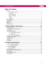
4.3.2.1 Inverter module A and B - socket X1B .............................................................................65
4.3.2.2 Motor connector for inverter module A and B ..................................................................66
4.3.2.3 Inverter module C - socket X1B ......................................................................................67
4.3.2.4 Motor connector for inverter module C ............................................................................68
4.3.2.5 Motor cable length ...........................................................................................................69
4.3.2.6 Interconnection of the motor ............................................................................................69
4.3.3 Temperature detection ........................................................................................................69
4.3.3.1 Connection of a KTY sensor ...........................................................................................70
4.3.3.2 Connection of a PT1000 sensor ......................................................................................70
4.3.3.3 Connection of the temperature input in operating mode PTC .........................................71
4.4.1 Assignment of the connector X1A ......................................................................................72
4.4.1.1 Terminal 15 „Enable“ .......................................................................................................74
4.4.1.2 Specification of the CAN bus
...........................................................................................74
4.4.1.3 Connection example 1 - Connection of the CAN client at T6
APD .............................................. 75
4.4.1.4 Connection example 2 - Assignment of both CAN interfaces with T6
4.4.2 Connection plug for X1A .....................................................................................................77
4.4.3 Bus interface X2A ...............................................................................................................78
4.4.3.1 Assignment of the Ethernet interface X2A .......................................................................79
.................................................................. 80
5.1 ECE R10 ..........................................................................................................................................80
5.2 Manufacturer´s declaration ..........................................................................................................81
6 Revision History .......................................................... 84
Summary of Contents for COMBIVERT T6APD
Page 2: ......

