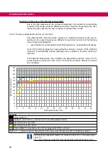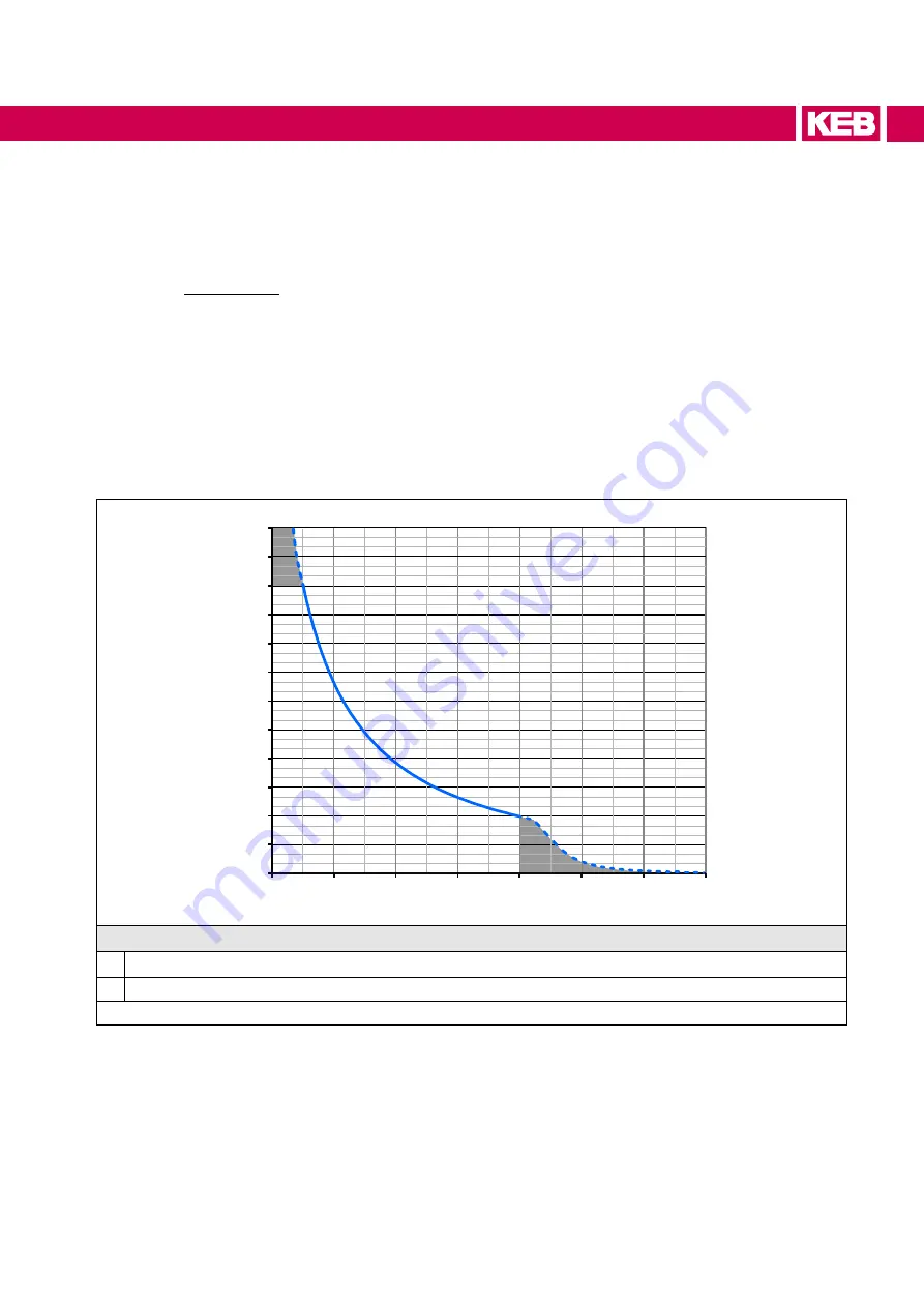
3.2.5.1 Overload characteristic (OL)
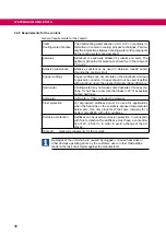
All drive inverters can be operated for 60 s at rated switching frequency with an utilization
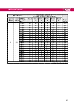
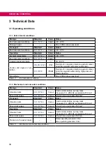
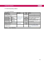
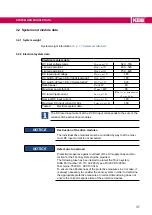
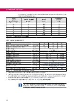
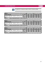
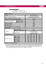
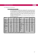
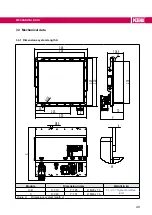
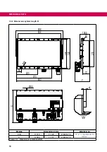
„Table 13: Electrical data of the inverter modules“
.
Restrictions:
• The thermal design of the heat sink is based on the rated output current and the
maximum surrounding temperature. At high surrounding temperatures and/or high
heat sink temperatures (for example, by preceding utilization nearby 100%) the
drive inverter can change to overtemperature error before triggering the protective
function OL.
• At low output frequencies or switching frequencies higher than the rated switch-
ing frequency, the frequency-dependent maximum current can be exceeded before
and error OL2 can be triggered =>
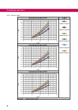
„3.2.5.2 Frequency-dependent maximum current
.
0
30
60
90
120
150
180
210
240
270
300
110
120
130
140
150
160
170
180
400
500
①
②
Motor current / drive inverter rated currrent / %
Overload characteristic (OC level 180%)
Release time / s
Legend
1
Thermal overload limit
2
Limitation by the software current limit (the limit can be set with parameter is35)
Figure 6:
Switch-off time t depending on the overload I/IN (OL) with the example of module A
On exceeding a load of 105 % the overload integrator starts. When falling below the
integrator counts backwards. If the integrator reaches the overload characteristic „Error!
overload (OL)“ is triggered.
After a cooling down period, the integrator can be reset now. The drive inverter must
remain switched on during the cooling period.
41
SYSTEM AND MODULE DATA
Summary of Contents for COMBIVERT T6APD
Page 2: ......

