4.3.2.5 Motor cable length
The maximum permissible resulting motor cable length per inverter module is 30 m.
Longer cables, standard cables with a larger capacitive coating against shield / PE and
cables with much bigger cross-section than required can:
• Reduce the overcurrent capability of the inverter.
•
Have a negative influence on the interference behaviour (radiation and cable-fed volt
-
age).
• Damage the device if necessary.
The resulting motor cable length for parallel operation of motors, or parallel installation
with multiple cables arises from the following formula:
resulting motor cable length = ∑single cable lengths x √
N
umber of motor cables
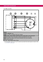
4.3.2.6 Interconnection of the motor
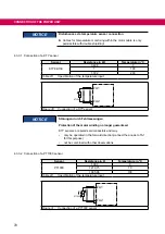
NOTICE
Incorrect behavior of the motor!
►
The connection instructions of the motor manufacturer are always
generally valid !
NOTICE
Protect motor against voltage peaks!
►
Drive inverters switch at the output with high dV/dt. Voltage peaks
that endanger the insulation system at the motor can occur espe-
cially in case of long motor cables (>15 m).
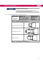
NOTICE
Connection of the drive in star connection!
►
The star point must not be earthed.
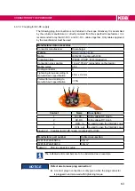
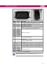
4.3.3 Temperature detection
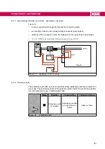
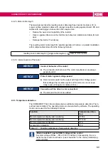
The COMBIVERT T6
APD
has implemented a switchable temperature detection. The in-
put has basic isolation. The operating mode can be selected by software. The operating
mode can be used for the following functions:
function
Temperature detec-
tion
Motor temperature display and monitoring
KTY84
Motor temperature display and monitoring
PT1000
Motor temperature monitoring
PTC
General error detection
PTC
Table 22:
Possible applications of temperature detection
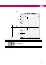
„basic insulation“ against SELV voltage of the control
A system voltage (Phase – PE) of 300 V is defined. Consequently, the con
-
nected sensors also must have a „basic insulation“ to the mains potential (e.g.
motor winding).
69
CONNECTION Of THE POWER UNIT
Summary of Contents for COMBIVERT T6APD
Page 2: ......


