background image

KC-P30 x-series

Web interface

Configuration manual V4.14

21

© KEBA

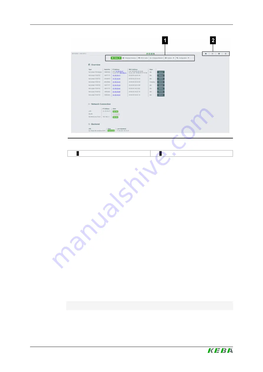
Fig. 4-6: Web interface start page

1

 ... Main menu

2

 ... User menu

The following chapters provide an overview of the possibilities of the web in-
terface. A detailed description of the individual configuration options can be
found directly in the web interface next to the respective configuration entry.

Also see about this

2

User menu [

}

 27]

4.1

Main menu

The main menu is divided into the following areas:

Status

Charging Sessions

RFID Cards

Charging Network

System

Configuration

4.1.1

Status

The page is divided into the following areas:

Overview

Here, basic information about all charging stations in the charging network is
displayed (such as serial number, IP address, operating state, etc.).

Summary of Contents for KeContact KC-P30 x Series

Page 1: ...KeContact KC P30 x series Charging Station Configuration manual V 4 14 Translation of the original instructions ...

Page 2: ...r technical developments Details presented may be subject to correction All rights reserved KEBA Energy Automation GmbH Reindlstraße 51 4040 Linz Austria www keba com emobility 43 732 7090 0 43 732 7309 10 kecontact keba com For information about KEBA and our subsidiaries please look at www keba com ...

Page 3: ... 2 2 Design of a local charging network master client 12 3 Configuration 15 3 1 Connection panel 15 3 2 DIP switch settings 15 3 3 Enabling the DHCP server 16 3 4 Configuration in series via USB stick 16 4 Web interface 20 4 1 Main menu 21 4 2 User menu 27 5 Functions 29 5 1 Load management in the local charging network 29 5 2 RFID authorization 30 5 3 OCPP backend 34 5 4 Smart Home Interface 36 5...

Page 4: ...regarding possible hazards The symbols used have the following meaning DANGER indicates an imminently hazardous situation which will result in death or se rious bodily injury if the corresponding precautions are not taken WARNING indicates a potentially hazardous situation which can result in death or seri ous bodily injury if the corresponding precautions are not taken CAUTION means that if the c...

Page 5: ... hazards Knowledge of current valid safety information the mode of operation of the charging station the displays and operating elements of the charging station basics of network technology basics of IT diagnostic options systematic fault analysis and rectification the setting options on the charging station 1 4 Warranty Only general maintenance work that is expressly permitted by KEBA may be perf...

Page 6: ... replaced or repaired by a specialist dealer or service partner 1 5 Notes on this document The manual is part of the product It is to be retained over the entire life cycle of the product and should be forwarded to any subsequent owners or users of the product The instructions contained in this manual must be followed precisely Failure to do so could result in the creation of potential sources of ...

Page 7: ...nuals and additional information are available on our website www keba com emobility downloads Designation Target group P30 operating instructions End customer Electricians P30 installation manual Electricians UDP Programmer s Guide Programmer FAQ End customer Electricians Service technicians ...

Page 8: ...ample network setup 1 Local charging network 2 Router Switch 3 Master charging station x series 4 Client charging station c series 5 Higher level network Internet 6 OCPP backend Only the P30 x series depending on the variant can be operated as master charging stations and only the c series as client charging stations The following chapters describe which network interfaces the P30 x series master ...

Page 9: ...er charging stations allowing to implement a charging network Information The Ethernet1 connector X4 LSA and the Ethernet2 connector X3 RJ45 are connected in parallel on the PCB and cannot be used at the same time The unused connection must be disconnected if necessary e g during servicing The Ethernet1 connection X4 is designed as a terminal block in LSA tech nology It is recommended to implement...

Page 10: ...e technical data of the WLAN module can be found in the Installation Manual Information Only a charging station that is operated as a single charging station can be connected to the router via WLAN A charging station that is part of a charging network master client network must always be connected to the router via LAN ...

Page 11: ...a pouch which is en closed with the mounting material The following steps are necessary to perform the configuration via a mobile device 1 Connect a mobile device to the WLAN access point 2 Access the IP address of the WLAN access point in a web browser on the mobile device 3 Perform configuration via the web interface see 4 Web interface 2 1 4 Mobile communications optional Certain device variant...

Page 12: ...g on the number of client charging stations the design of a local charging network is implemented differently 1 client charging station Direct connection The client charging station is connected directly to the master charging station Multiple client charging stations Connection via router or switch The client charging stations are connected to the master charging station via a router or switch To...

Page 13: ... In this case the master charging station must be configured as a DHCP server The IP address is then assigned to the client charging station by the master charging station 2 2 3 Connection via router or switch If there are multiple client charging stations these must be connected to the master via a router or switch The connection of the charging station to the router switch is made via LAN Fig 2 ...

Page 14: ...for communication in the charging network For the correct communication in the charging network the ports below must be enabled network internally Information If necessary contact your network administrator to enable the ports Port Protocol Definition Description 49153 TCP Within the network Socket of the charging station 15118 TCP Within the network Link connection between the charg ing stations ...

Page 15: ... the housing cover and the connection panel cover must be removed The description of removing the covers and the connection panel can be found in the Installa tion Manual 3 2 DIP switch settings This DIP switch setting must be made for each master and client charging station to enable charging station communication Caution Possible damage to the DIP switches The DIP switches are rocker switches an...

Page 16: ...nted via switch The DHCP server on the master is deactivated in the delivery state and can be activated using the configuration via USB stick or in the web interface 3 4 Configuration in series via USB stick There is the option of configuring multiple P30 x series units with the same settings In this process the configuration of a P30 x series is saved on a USB stick and then transferred to other ...

Page 17: ...a USB stick to additional charging stations 3 4 2 Read out configuration In order to be able to transfer the configuration of one P30 x series to addi tional P30 x series the USB stick must be connected to the USB interface in the connection panel of the operationally ready and already configured charging station The charging station automatically transfers the configura tion to the USB stick and ...

Page 18: ... equal sign The value is located to the right To adapt and delete the specific configurations proceed as follows 1 Open the configuration file with a text editor 2 Change the following entries AmountConnectors x The number of charging stations in the charging network must be adapted here 3 Delete the following entries completely ChargeBoxIdentity xxx Connect2ConnectorSerial x xxx HOTSPOT_SSID xxx ...

Page 19: ... Information Invalid settings are not applied 3 4 4 Import configuration To load the configuration into another P30 x series the USB stick must be plugged in to the desired charging station The configuration will be imported automatically and adopted after a restart ...

Page 20: ...ation label Router with integrated DHCP server The charging station automatically receives an IP address via the DHCP server of the router The IP address is displayed on the charging station display when the charging station is re started The IP address can also be determined via the router Master with local DHCP server The local DHCP server has been activated for the master which automatically gi...

Page 21: ...ns can be found directly in the web interface next to the respective configuration entry Also see about this 2 User menu 27 4 1 Main menu The main menu is divided into the following areas Status Charging Sessions RFID Cards Charging Network System Configuration 4 1 1 Status The page is divided into the following areas Overview Here basic information about all charging stations in the charging netw...

Page 22: ...locked Network Connection Here information about the network interfaces LAN mobile communica tions WLAN and WLAN Access Point of the master is displayed Backend Information about the OCPP backend such as connection status and ad dress is displayed here 4 1 2 Charging Sessions This page displays details about the charging sessions of the last 12 months The Export button lets you export the charging...

Page 23: ... power failure This setting is disabled by default Operating Mode Here is determined whether the charging station is operated as a single charging station or as a master charging station in a charging network The number of clients must be entered for a charging network In addition all attached client charging stations must be entered with their respective se rial numbers Otherwise the client charg...

Page 24: ... Signed measurement data export Signed log data export Restart System Certificates Software Update The currently installed software versions are displayed A software update can also be performed here Mobile Communications Info Information about the mobile communications connection is displayed and the connection to the selected mobile communications network can be tested Logging The event log can ...

Page 25: ...ates For an encrypted connection certificates can be imported in pfx format A connection to the web interface can be encrypted The following certificates are available WebUI certificates Certificate Purpose Https WebUI Encrypted connection to the web interface Restart System The master can be restarted with this button 4 1 6 Configuration The configuration of the charging station is carried out in...

Page 26: ...ommunication WLAN Access Point SIM APN connec tion data can be selected and configured Routing Settings for necessary routing can be made here Proxy All the necessary configurations for using a proxy server can be found in this part OCPP All the necessary configurations for connecting to an OCPP backend can be found in this part The displayed configuration options vary depending on the selected tr...

Page 27: ... of the charging station describing various processes of the charging station The language of the text can be changed the display duration can be configured and the display text itself can be changed The text display is limited to 20 characters and no umlauts or special char acters can be used The abbreviations Wh and kWh must not be used in the display texts as they may be misleading to the user ...

Page 28: ... access the charging station via an encrypted connection These settings can also be configured on the OCPP backend Log level For error diagnosis it can be necessary to record the operations of the charging station in detail This can be enabled in this area of the DEBUG mode To ensure that the recorded data quantity is not too large the dura tion for the detailed recording must also be specified Re...

Page 29: ...ion set maximum current per phase number of active charging sessions on this phase If insufficient power is available for an additional charging process in the charging network set minimum current is underrun the new charging process will be lined up Every 15 minutes an active charging session is paused in sequence lined up at the back of the line and the next charging session in the line continue...

Page 30: ...on is enabled and disabled in the web interface of the master In the case of a local charging network without a higher level OCPP back end all RFID cards must be taught in at the master Up to 1000 RFID cards can be stored After teaching in the permitted RFID cards are stored at the master and are managed by it in the charging network It is not possible to teach in RFID cards at a client charging s...

Page 31: ...ven if they are not stored locally at the charging station Only those RFID cards that are stored locally at the charging station and have a status other than AC CEPTED are rejected OfflineLocalAuthorization Only RFID cards stored locally at the charging station with the status of ACCEPTED are accepted OfflineNoAuthorization All RFID cards are temporarily accepted As soon as the con nection to the ...

Page 32: ... and hold the Service button in the connection panel until the second signal tone is sounded approx 10s The charging station will then automatically perform a restart deleting all previously taught in RFID cards if necessary 2 The charging station will be available again after 30 seconds 3 After the waiting time the first three segments of the led bar are illumi nated A master RFID card can be tau...

Page 33: ...harging station where the RFID card may be authorized All or only certain charging stations in the charg ing network can be enabled for the RFID card 5 2 4 RFID authorization with OCPP backend connection If the charging station or a charging network is controlled by an OCPP back end please note the following Teach in RFID cards All RFID cards must be centrally taught in at the OCPP backend Authori...

Page 34: ...n offers the option of being connected to a central man agement system via the Open Charge Point Protocol OCPP OCPP as an open application protocol makes it possible to connect any central manage ment system to the charging station regardless of the manufacturer or sup plier The following OCPP versions are supported OCPP 1 5 via SOAP OCPP 1 6 via SOAP or JSON Connection to an OCPP backend When con...

Page 35: ...gured on the charging station Custom TCP Access to external outgo ing Port at which the OCPP backend can be reached 123 UDP Incoming and outgoing Port for the time server of the charging station Supported messages The following table provides an overview of the supported messages Message OCPP 1 5 OCPP 1 6 Authorize x x BootNotification x x ChangeAvailability x x ChangeConfiguration x x ClearCache ...

Page 36: ...for integration into a smart home 5 5 Integration of external meters The charging station can read out the measured values from external meters via Modbus TCP This allows an intelligent calculation of the charging cur rent provided to the vehicle and the charging process is optimized The measured values that are read out are included in the charging current spec ification The following graphic sho...

Page 37: ...gy supply from the power grid via meter 5 The charging station can use this information to regulate the maximum charging current for a charging network such that the maximum current and power defined in the web interface is not exceeded for details see 5 5 3 Settings 5 5 1 Connection When connecting external meters please note the following The connection is made via the Ethernet1 connection X4 LS...

Page 38: ...n instructions of the meter manufacturer 5 5 3 Settings The Modbus TCP feature is disabled by default If an external meter with a Modbus TCP network interface has been installed in the system it must be configured in the web interface in advance The maximum permitted charging current per phase and the maximum per mitted charging capacity for the entire charging network can be configured in the web...

Page 39: ... vehicle is plugged in at the charging station Information The software update can take up to an hour The update process is indi cated by a slow orange flashing of the LED bar After the software update the charging station restarts automatically The LED bar will flash blue or green depending on the authorization setting Information The power supply must not be interrupted during the software updat...

Page 40: ...e Choose a file button 5 Start the update process with the Upload Install button 6 2 2 Software update via USB stick For a software update using a USB stick this function must be activated in the configuration web interface To perform a software update via a USB stick proceed as follows 1 Download the current software for the charging station keb file 2 Plug the USB stick into a PC 3 Format the US...

Page 41: ...The software update for the entire charging network can be performed via the OCPP backend To perform the software update an FTP link is required The information downloaded from our website along with the software update contains the FTP link For details on using the FTP link see the OCPP backend manual ...

Reviews: