background image

3  Installation 

The welding equipment is equipped with power  voltage compensation  device.  It  keeps the

machine work normally when power voltage fluctuating ±15% of rated voltage.
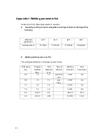
When using long cable, in order to reduce voltage drop, big section cable is suggested. If the
cable   is   too   long,   it   will   affect   the   performance   of   arcing   and   other   system   function,  it   is

suggested to use the recommend length.

Make sure the intake of the machine is not covered or blocked to avoid the malfunction of
the cooling system.

Use ground cable whose section no less than 6mm

2

 to connect the housing and earth. The

method is to connect the grounded interface in the back to the earth device, or make sure
the earth end of power interface has been reliably and independently grounded. Both ways

can be used together for better security.

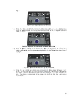
Installation Procedures

Correct Installation of MIG

a) Connect the gas cylinder with CO

2  

decompression flow mete tightly to CO

2

 mouth behind

the machine via air tube.

b) Insert the swift plug of earth cable into socket at the front panel.
c)

Set the wire wheel with wire on the wheel axis, the wheel hole should be matched with the

wheel fixer.

d) Choose wire slot according to wire size.
e) Loosen the screw of wire-pressing wheel, pit the wire into slot via wire-lead tube, adjust the

wire-pressing wheel to keep wire fix from gliding, but strength should be suitable in case

the wire distorts and affects wire sending.

f)

Wire roll should turn clockwise rotation to let out wire, to prevent wire from gliding; wire is
usually set to the fixed hole on the wheel side. To prevent the bent wire from getting stuck,

please cut off this part of the wire.

g) Put and tighten the torch on the output socket and put the wire into the torch by hand.

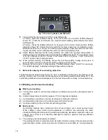
Correct Installation of TIG

a) Connect   the   shielded-gas   source  correctly.  The   gas   supplying   route  shall  include   gas

cylinder, argon decompression flow meter and gas pipe. The connecting parts of the gas

pipe should be fastened by hose clamp or other objects, in order to prevent leakage and
air-in.

b) Connect the plug of TIG torch to “-“of the front panel, and fasten it clockwise. 
c)

Connect the plug of TIG torch to the relative interfaces of panel and fasten the screw.

d) Connect one end of the earth clamp cable to “+” of the front panel, and fasten it clockwise,

the other end clamp the workpiece.

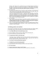
Correct Installation of STICK 

a) Make sure cable with electrode holder and quick plug connected well. Connect the quick

plug to the socket “-” of the machine, and fasten it clockwise tightly.

b) Connect the quick plug at one end of the cable into the socket “+” of the machine, and

10

Summary of Contents for MIG 160GDM

Page 1: ...MIG 160GDM 180GDM WELDING MACHINE USER MANUAL ...

Page 2: ......

Page 3: ...s after this sign means there is some potential danger which may cause hurt or property lose if it is not followed The words after this sign means there is potential risk which may cause equipment fault or break if it is not followed Version Version YF TAE 0059 A0 Released at 30th 03 2016 The contents of this manual are updated irregularity for updating of product The manual is only used as operat...

Page 4: ... 4 Operation 13 4 1 Front panel layout 13 4 2 Operation instruction 13 4 3 Welding environment and safety 16 4 4 Welding problems and resolution 17 5 Daily maintenance and checking 18 6 Trouble shooting and fault finding 21 Appendix Ⅰ Welding parameter list 22 Appendix Ⅱ Circuit diagram 23 2 ...

Page 5: ... cause choke Spark and hot workpiece after welding may cause fire Bad connected cable may cause fire Uncompleted connection of workpiece side circuit may cause fire Never weld on the case of tinder stuff or it may cause explode Never weld airtight containers such as slot pipe etc or it may break Arc ray may cause eye inflammation or skin burnt Spark and residue will burn your eyes and skin Topplin...

Page 6: ...on sleeve or even exposed conductor Do ensure well isolation of wire connection Never use the device when the enclosure is removed Never use broken or wet insulation gloves Use firenet when work at high position Check and maintain regularly don t use it until the broken parts are fixed well Turn off the power when not in used Follow the national or local related standard and regulations when using...

Page 7: ...tor Read the manual of gaseous regulator carefully before using it and pay attention to the safety notes Fix the gas cylinder with appropriative holder and other relative parts Never put the cylinder under high temperature or sunshine environment Keep your face away from the gas cylinder exit when opening it Put on the gas shield when it is not used Never put the torch on the gas cylinder The elec...

Page 8: ...le signal cable and phone cable b Wireless electric as well as TV radiation and reception equipment c Computer and other control equipments d Safety recognition equipment etc Such as supervise of industrial equipments e Health of people around Such as personnel using heart pacemaker or audiphone f Equipments for adjustment and measurement g Anti disturb capability of other used equipments Users sh...

Page 9: ...eters easily Our CO2 gas shielded welding machine is equipped with unique electronic reactor circuit which can precisely control the short circuiting transfer and mixed transfer resulted in better performance than other machines Compared with silicon controlled welding machine and tapped welding our products have the following advantages stable wire feed rate portable energy saving electromagnetic...

Page 10: ...IG Output voltage V 20 4 26 4 MMA 16 5 22 MIG 10 4 16 4 TIG No load voltage V 64 Duty cycle 40 C 25 MMA 30 MIG 35 TIG Power factor 0 73 Efficiency 80 Type of wire feeder Internal Wire feeding speed m min 3 12 Post flow time S 1 Wire diameter mm 0 8 Insulation grade F Housing protection grade IP21 Welding thickness mm 2 10 Weight kg 8 Overall dimension L W H mm 386 170 300 8 ...

Page 11: ...G 10 180 TIG Output voltage V 20 4 26 4 MMA 16 5 23 MIG 10 4 17 2 TIG No load voltage V 64 Duty cycle 40 C 25 Power factor 0 73 Efficiency 80 Type of wire feeder Internal Wire feeding speed m min 3 12 Post flow time S 1 Wire diameter mm 0 8 Insulation grade F Housing protection grade IP21 Welding thickness mm 2 10 Weight kg 8 Overall dimension L W H mm 386 170 300 9 ...

Page 12: ...oosen the screw of wire pressing wheel pit the wire into slot via wire lead tube adjust the wire pressing wheel to keep wire fix from gliding but strength should be suitable in case the wire distorts and affects wire sending f Wire roll should turn clockwise rotation to let out wire to prevent wire from gliding wire is usually set to the fixed hole on the wheel side To prevent the bent wire from g...

Page 13: ...oice is made it will cause unstable arc more spatters and conglutination If such problems occur please change the polarity of the fastened plug It should adopt negative connection when welding with alkaline electrode while positive connection when welding with acid electrode This procedure shall be operated by electrician Connect proper power cable to the distribution box with corresponding capaci...

Page 14: ...Installation diagram TIG Installation diagram STICK 12 ...

Page 15: ...mode switch key Select the welding mode as MMA TIG MIG CO2 and MIG MIX 4 Multifunctional data display 4 2 Operation instruction The starting up display Switch on the welding power source the front panel displays as Fig 1 After the Welding current display or press any key or knob on front panel flashes for 5 seconds the machine enters into the welding mode that saved in the last shutdown Fig 1 the ...

Page 16: ...ed f When perform welding the display shows the real time welding voltage and current 5 seconds later it returns to the preset current state Operation instruction under TIG mode a When welding stops press the Welding mode switch key the TIG indicator lights up and it turns into TIG mode b Under TIG mode the multifunctional data display is as shown in Fig 3 Fig 3 The preset current under T TIG mode...

Page 17: ...ain display shows the fine adjusting range of inductance Turn the Data adjusting knob to set the range from 10 to 10 as Fig 6 Fig 6 Fine adjustment of inductance range under MIG mode e Press the switch of MIG gun It starts wire inching And the Main display shows as Fig 7 When connected w ith MIG gun press the torch switch for 5s without welding the internal wire spool in the machine starts to rota...

Page 18: ...ys welding voltage and wire speed Malfunction display of overheating protection The Multifunctional data display shows P EH and flashes continuously the machine is not working normally now Only when the temperature of the welding machine falls below 55 the overheating malfunction would disappear and the machine works normally no need restart up 4 3 Welding environment and safety Working surroundin...

Page 19: ...able range If power voltage is exceeding allowable range limits it can damage the components of machine The operator should understand this situation and take preventive measures d There is a grounding cable behind welding machine with a mark Before operation welding crust must be grounded reliably with cable in order to prevent static electricity and accidents for electricity leaking 4 4 Welding ...

Page 20: ... sand paper and connect again d Prevent water from entering into the machine and prevent the machine from getting moist If any blow and dry Measure the insulation with megohmmeter to make sure it is qualified to use e If the welding machine is not used for a long time pack the machine in original package and store in dry surroundings f Every time the wire feeder operates for 300hours grind the ele...

Page 21: ...of material Electric hole If installation fixed Reason of torch screw thread damage Damage of its head and hole blocked or not Reason of unstable arc and broken arc Wire sending tube Check the extended size of the pipe Change when less than 6mm when the extended part too small the arc will be unstable Wire diameter and the tube inner diameter match or not Reason of unstable arc please use the suit...

Page 22: ...ove and wearing out of pressed wire the narrowing of its contact surface Lead to unstable arc and wire sending CABLE Position Checking keys Remarks Torch cable 1 If torch cable over bended 2 If the metal connecting point of mobile plug loosen 1 Cause poor wire sending 2 Unstable arc if cable over bended Output cable 1 Wearing out of the cable insulated material 2 Cable connecting head naked insula...

Page 23: ...tact dealers The meter shows Fan works normally No welding output Check if all the sockets in the machine are connected well There is open circuit or badness of connect at the joint of output terminal The control cable on the torch is broken off or the switch is damaged The control circuit is damaged contact to dealers The meter shows Fan works normally Abnormal indicator lights It might be over c...

Page 24: ...elding current 70 100A 110 140A 170 220A 230 280A Welding variables when use TIG TIG welding specifications of stainless steel as follows Thickness mm Tungsten diameter mm Wire diameter mm Type of butt joint Welding current A Gas flow L min 0 5 1 0 1 0 plain butt joint 35 40 4 6 0 8 1 0 1 0 wire filling 35 45 4 6 1 0 1 6 1 6 40 70 5 8 1 5 1 6 1 6 50 85 6 8 2 0 2 0 2 5 2 0 80 130 8 10 3 0 2 5 3 0 2...

Page 25: ...URRENT A OUTPUT OUTPUT 24V GND LP CURRENT B D riv e G 1 D riv e E 1 D riv e E 2 D riv e G 2 15V VRD VRD P W M M O T E N M O T C U R M O T SWA SWB POWER EN VGND 3 3V GND SPEED 1 2 CON3 备注 0 CON1 连接气阀线圈 1 CON2 24V 连接 风机 2 CON3 连接温度传感器 3 CON4 连接焊接启动开关 4 CON5 CON7 和 联结 处理人机界面 5 CON6 连接送丝电机 6 CON8 连接原边电流采集 7 P2 连接次边霍耳传感器 7 P3 连接机箱接地点 8 PCON2 连接输出 端口 9 220R 100K 1R 2010 为 封装 2 1 3 Q1 2 1 3 Q3 R21 R23 C1...

Page 26: ...24 ...

Reviews: