background image

 Assembling the Step Over

11

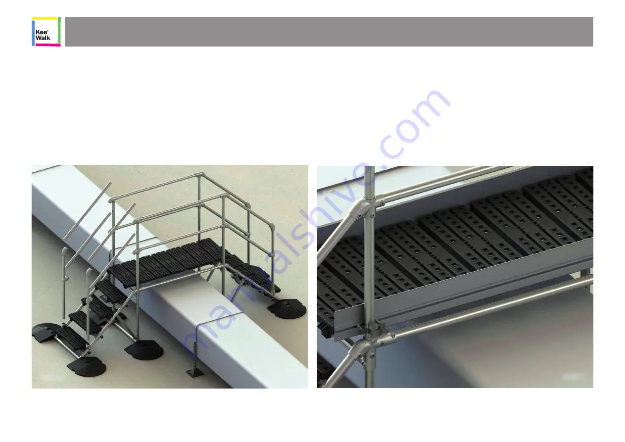
STEP 6 - Assemble the remaining guardrails and toe board 

Take the forward assembled uprights (Part B) and insert into the 29-7 fitting present on the stair 

assembly and loosely tighten the fittings.

Starting on one side, insert the two inclined hand rails (Part C) into the 326-7 fittings present on the 

rear upright, and manoeuvring the front upright forward insert both rails in the 29-7 and the 55-7 

fittings, move the upright back to its upright position and loosely tighten. 


Using a spirit level, ensure the forward upright is plumb and level in the X and Y plane, once level, 

tighten all grub screws to 39Nm.   

Repeat for other side of staircase, and then repeat the entire procedure for the other staircase.

STEP 7 – Fitting toe board 

Locate toe board (Part E) inboard of bridge platform and pick the TBFP1  fixing packs and TB3-7 

toe-board fixing clamps.  

Insert the M12 bolts into the extruded channel, and locate 1 bolt either side of each upright as 

shown in the illustration.  

Locate the TB3 clip onto the bolts, fits the nuts and washers. 

Level the toe board and tighten the fixings to 25Nm.  

STEP 6

STEP 7

Summary of Contents for WALK Step Over

Page 1: ...KEE WALK Step Over Operation Maintenance Manual S A F E T Y A T T H E H I G H E S T L E V E L ...

Page 2: ...atforms for the Major Roof Types 6 Assembling the Step Over 8 Finished Step Over 13 Kee Walk Mini Step Over 14 Assembling and fixing the Mini Step Over Fixed Version 15 Assembling and fixing the Mini Step Over Free standingg 16 Kee Walk Step Over System Recertification 17 Contents ...

Page 3: ...designed to be fully adjustable and can accommodate heights from 600mm up to 1400mm DURABILITY KEE WALK Step Over is available in a range of high quality finishes The components are supplied with a galvanised finish carried out to BS EN ISO 1461 and ASTM A53 Hot Dip Galvanised Coatings Specification and Testing Methods giving an average coating of between 65 85 microns All cast clamps have Threadk...

Page 4: ...ed by the application of powder coating to EN 13438 MATERIALS Steel tubing to EN 10255 42 4mm diameter tube x 3 2mm wall thickness All steel components galvanised to BS EN ISO 1461 All fixings are hot dipped galvanised to BS EN ISO 1461 All cast clamps have Threadkoat applied to all tapped holes All grub screws are carbon steel and have Kee Koat protection applied to ensure minimal maintenance Whe...

Page 5: ... components The exact number of individual components depends upon the length and construction of a specific system All fittings are cast from malleable cast iron to BS EN 1562 and galvanised to BS EN ISO 1461 and full part numbers for reference are detailed below Aluminium toe board is 6062 T6 grade Note A complete list of all parts and details on the total weight of the Step Over system is provi...

Page 6: ...ep Over System s Components 4 Weighted foot assembly Front guardrail upright Step module guardrails Bridge module guardrails Toe board assembly Bridge module Back upright assembly Stair tread assembly A B C D E H F G ...

Page 7: ...Checking the Step Over System s Components 5 Exploded view of system layout and location of components and sub assemblies A B C D E H F G ...

Page 8: ... suit all major roof types The Step Over range consists of a number of different configurations to suit the major flat roof types Membrane and concrete roof type platforms are standard units whereas metal profile roofs are bespoke to the particular application requiring a survey and semi bespoke base plate layout design This will ensure a perfect fit and other height width length variables can be ...

Page 9: ...o suit the major flat roof types Membrane and concrete roof type platforms are standard units whereas metal profile roofs are bespoke to the particular application requiring a survey and semi bespoke base plate layout design This will ensure a perfect fit and other height width length variables can be accommodated as a bespoke solution contact Kee Safety for further information Where access is lim...

Page 10: ...and add the weights to either end of the tube ensuring the weights are inserted fully Tighten the 74 7 grub screws to 39Nm Manoeuvre the assembled rear upright into position at the point of install Tighten all grub screws to the required 39Nm torque setting 5 Installation should only be carried out once the design has been verified in the Step Over Configurator and the installer has been fully tra...

Page 11: ...uprights Add the Kee Walk bridge tread assembly to the substrate ensuring it is centred left right and front back and fix into place using the 105 7 fittings to the underside and securing in place with self drilling screw Repeating all sub sets of step 1 to build other side of platform uprights Inserting bridge subframe tubes into uprights at obstruction Inserting bridge subframe tubes into uprigh...

Page 12: ...sembly Locate upper tube from staircase and brace tube in the correct orientation to meet the corresponding tube sockets in the lower 29 7 and upper 326 7 fitting Starting with the upper tube manoeuvre the lower tube down towards the stair assembly and lower the staircase so that the upper tube can be inserted Into the 326 7 fitting Before fitting fully locate the lower tube into 29 7 fitting Push...

Page 13: ...its upright position and loosely tighten Using a spirit level ensure the forward upright is plumb and level in the X and Y plane once level tighten all grub screws to 39Nm Repeat for other side of staircase and then repeat the entire procedure for the other staircase STEP 7 Fitting toe board Locate toe board Part E inboard of bridge platform and pick the TBFP1 fixing packs and TB3 7 toe board fixi...

Page 14: ...are re tightened on completion The Stair rail and tread assemblies are pre assembled at Kee Safety so no major adjustments should be required STEP 9 Check and recheck all grub screws and finalise assembly Once all treads are level the platform is fully assembled and the toe board is present ALL grub screws are to be torqued to 39Nm Starting at the lower left staircase working from the lowest point...

Page 15: ... APPLICATION Whilst we can supply Step Over platforms for membrane asphalt PVC and concrete from stock owing to the vast variety of roofing profiles and fixing methods it is not possible to carry stocks of Step Over platforms specific to each roofing type and manufacturer A bespoke solution is available following a site survey to best advise on the product that is most suited to the requirement co...

Page 16: ...ce Weight 68 63kg MINI STEP 200MM CLEARANCE FREE STANDINGG With recycled PVC weighted bases to eliminate the need to fix the unit to the roof this unit is designed to clear obstacles up to 400mm in height STMFS2003 433mm clearance Weight 83 93kg STMFS2004 673mm clearance Weight 85 43kg GENERAL Two options are available free standing which the unit stands on two 26kg base weights or fixed which can...

Page 17: ... fixing the Mini Step Over Fixed Version b Peel back rubber end cap and slide 2no M8 bolts onto the end of the aluminium extrusion Replace rubber end cap Pass M8 bolts through 62 6 fitting and secure using M8 fixings and a 13mm spanner Using a torque wrench tighten to 15N m Repeat process for 3 other long legs c Turn unit over and place over obstacle Either fix to surface or sturdy obstacle using ...

Page 18: ...ngs Place weighted bases in position either side of obstacle Lower platform into position ensuring 199 6 fitting lines up with the aluminium extrusion as per diagram c Ensure all fixings are tight with fittings torqued to 29N m and M8 nuts tightened to 15N m c Ensure all fixings are tight with fittings torqued to 29N m and M8 nuts tightened to 15N m Assembling and fixing the Mini Step Over Free st...

Page 19: ... or tampered with by un authorised persons Check all base feet are in contact with the roof Check all counter weights where present on original drawing are in place as per the original drawing This is essential for longevity of the roof Check all grub screws are in place and correctly torqued Check the general height and level of the system including the leg centres and platform overall configurat...

Page 20: ...or omissions Kee Safety Ltd reserves the right to alter or withdraw products without prior notice Kee Safety Ltd accepts no responsibility for any loss or damage arising from improper use of their products 2016 Kee Safety Ltd All Rights Reserved KS KWSOMM_UK_v2 1018 Kee Safety Ltd Cradley Business Park Overend Road Cradley Heath West Midlands B64 7DW Tel 44 0 1384 632188 Fax 44 0 1384 632192 Email...

Reviews: