7.1
3
Maintenance
7.1
3
Guide Wheel Adjustment
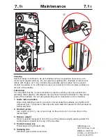
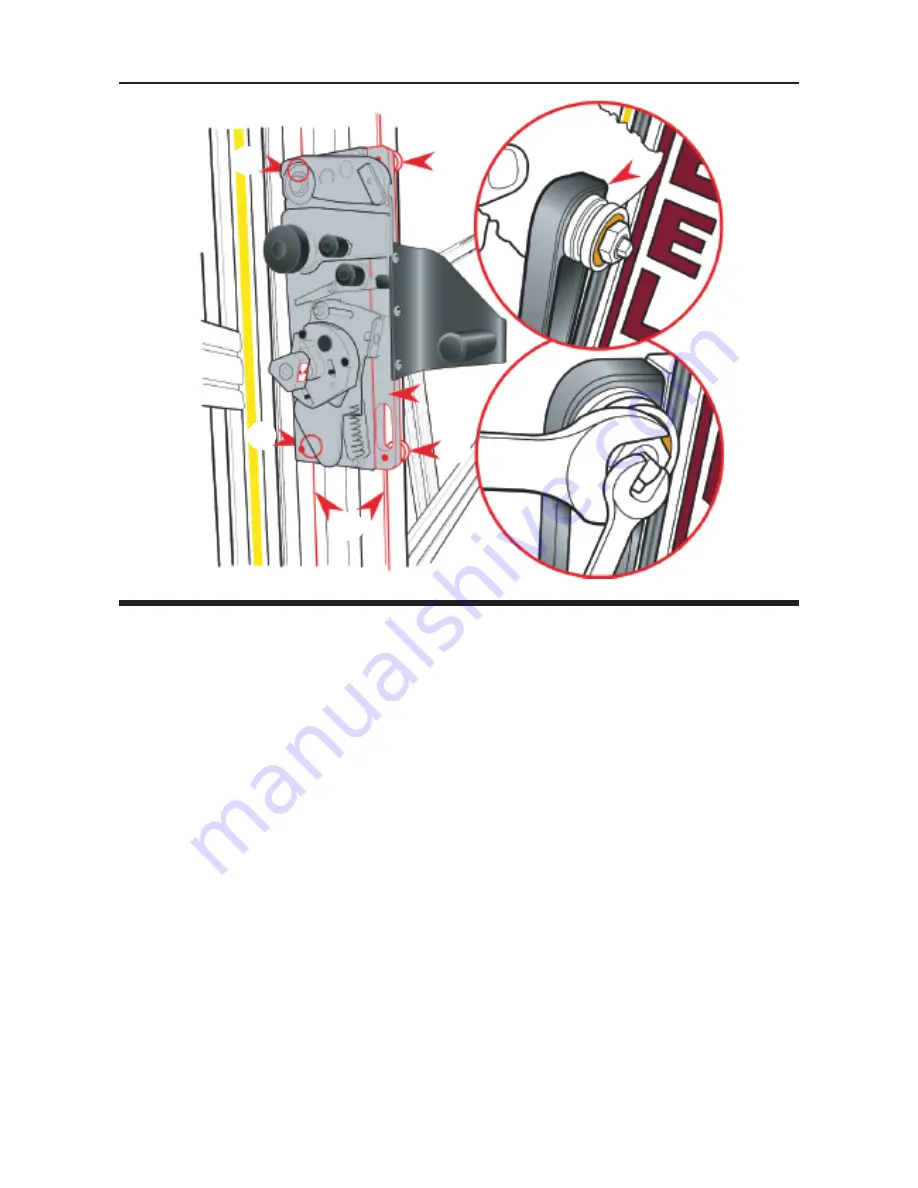
The Cutting Head slides up and down on two stainless steel Guide Rails (1) that are
embedded into the Slideway (2). There are four grooved Guide Wheels that run on the
rails, the two furthest away are fixed (A) and the two closest are adjustable (B). These
Guide Wheels are adjusted in the factory and should not under normal circumstances
require re-adjustment. However, the adjustment check and procedure is listed in the
event that the Cutting Head needs to be removed for any reason:
Adjustment Check:
The steel bar with the oval holes, the Spring Block (4), holds the two adjustable wheels
and is designed to flex, a small amount, like a spring and add tension so the Guide
Wheels are pressed onto the Rails. It is important that the tension is set correctly, use
a 0.15mm (0.006") feeler gauge or a stout piece of paper to measure the gap under the
Spring Block as shown. If the gap is too large or too small the adjacent wheel will
need adjusting.
Wheel Adjustment:
The Shafts that the adjustable wheels run on are eccentric and move the wheel into or
away from the rail as it is rotated.
n
Using a 13mm spanner on the Locking Nut and a 5mm spanner (or grips) on the
square end of the Shaft hold the Shaft still and loosen the Locking Nut by about half
a turn.
n
Rotate the Shaft clockwise whilst using a feeler gauge or paper as above to measure
the gap under the Spring Block. If the Shaft will not rotate any further and the correct
gap has not been achieved, turn it anti-clockwise and the correct adjustment should
be obtained within one full rotation of the Shaft.
n
When the correct gap appears hold the Shaft still and tighten the Locking Nut.
4
1
A
A
B
B


