F96VTN and G96VTN: Installation, Start-up, Operating and Service and Maintenance Instructions
Manufacturer reserves the right to change, at any time, specifications and designs without notice and without obligations.
44
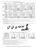
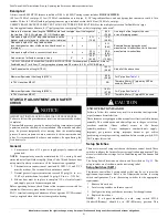
When installing vent systems pipe lengths of 10 ft. (3 M) or less, use the
smallest allowable pipe diameter. Using a pipe size greater than required
for short venting systems may result in loss of efficiency, incomplete
combustion, flame disturbance, or flame sense lockout.
For vent systems longer than 10 ft. (3 M), any larger diameter vent pipe
shown in
FOR THAT SIZE FURNACE
may be used.
Combustion Air and Vent Piping Insulation
Guidelines
NOTE:
Use closed cell, neoprene insulation or equivalent.
The vent pipe may pass through unconditioned areas. The amount of
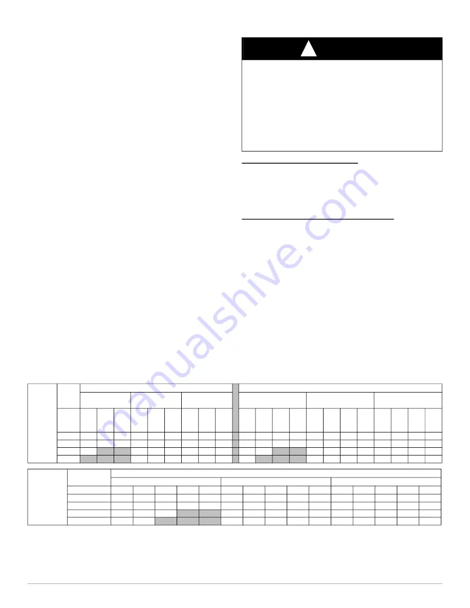
exposed pipe allowed is shown in
.
1. Using winter design temperature (used in load calculations), find
appropriate temperature for your application and furnace model.
2. Determine the amount of total and exposed vent pipe.
3. Determine required insulation thickness for exposed pipe length(s).
4. When combustion air inlet piping is installed above a suspended
ceiling, the pipe
MUST
be insulated with moisture resistant
insulation such as Armaflex or other equivalent type of insulation.
5. Insulate combustion air inlet piping when run in warm, humid
spaces.
6. Install the insulation per the insulation manufacturer’s installation
instructions.
NOTE:
Pipe length (ft. / M) specified for maximum pipe lengths
located in unconditioned spaces cannot exceed total allowable pipe
Configure the Furnace
Near Furnace Vent Connections
Offsets in the vertical portion of the vent pipe should be made with 45
deg. elbows instead of 90 deg. elbows. Short horizontal runs of vent pipe
are difficult to pitch correctly and may trap water in the vent pipe.
Trapped water in the vent pipe may result in nuisance pressure switch
tripping.
Install the Vent and Combustion Air Pipes
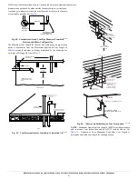
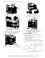
With the furnace installed in the required position, remove the desired
knockouts from the casing. It will be necessary to remove one knockout
for the vent pipe and the other knockout for the combustion air
.
Use a flat blade screwdriver and tap on the knockout on opposite sides,
where the knockout meets the casing. Fold the knockout down with duct
pliers and work the knockout back and forth until it is removed. Trim
any excess metal from the knockout with tin snips.
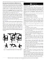
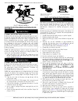
The vent elbow can be rotated to the required location on the casing if
necessary. See
. To rotate the vent elbow:
1. Loosen the clamp on the inlet of the vent elbow attached to the
inducer.
2. Rotate the vent elbow to the required position. There are rounded
notches on the vent elbow to align it with the inducer housing for
each orientation.
3. Tighten the clamp around the vent elbow. Torque the clamp to 15
Table 16 – Maximum Allowable Exposed Vent Lengths in Unconditioned Space Insulation Table - Ft. / M
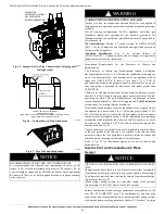
WARNING
!
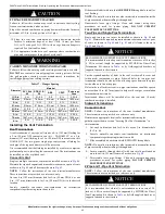
CARBON MONOXIDE POISONING HAZARD
Failure to follow this warning could result in personal injury or death.
To route the vent pipe and combustion air pipe through the furnace, the
manufacturer supplied kit must be used. Failure to properly seal the
blower compartment from the furnace vestibule could result in the
circulation of carbon monoxide throughout the structure. The vent pipe
and combustion air pipe must be a continuous pipe while passing
through the blower compartment. Seals supplied in this kit must be
installed per the instructions provided. Follow all procedures outlined
in these instructions.
Winter
Design
Temp °F
Unit
Size
40,000* BTUH
60,000 BTUH
Uninsulated
3/8-in.
Insulation
1/2-in.
Insulation
Uninsulated
3/8-in. Insulation
1/2-in. Insulation
Pipe
Dia.
in.
1 ½
2
2 ½ 1 ½
2
2 ½ 1 ½
2
2 ½
1 ½
2
2 ½ 3
1 ½
2
2 ½
3
1 ½
2
2 ½ 3
20
20
20
20
20
50
45
20
60
50 20
30
30
25
20
75
65
60
20
85
75
65
0
10
5
5
20
25
20
20
30
25 15
15
10
10
20
40
30
25
20
45
40
30
-20
5
20
15
10
20
20
15 10
5
20
25
20
15
20
30
25
20
-40
15
10
5
15
15
10 5
20
15
15
10
20
20
15
10
Winter
Design
Temp °F
Unit Size
80,000 BTUH
Uninsulated
3/8-in. Insulation
1/2-in. Insulation
Pipe Dia. in.
1 ½
2
2 ½
3
4
1 ½
2
2 ½
3
4
1 ½
2
2 ½
3
4
20
15
40
40
35
30
15
50
90
75
65
15
50
70
70
70
0
15
20
15
10
5
15
50
45
35
30
15
50
50
40
35
-20
15
10
5
15
35
30
20
15
15
40
30
25
15
-40
10
5
15
25
20
15
5
15
30
25
20
10

