INSTALLATION INSTRUCTIONS
R−410A, Two−Stage Split System Air Conditioner
421 01 6002 01
11
COMPRESSOR OPERATION
The basic scroll design has been modified with the
addition of an internal unloading mechanism that opens
a by−pass port in the first compression pocket, effectively
reducing the displacement of the scroll. The opening and
closing of the by−pass port is controlled by an internal
electrically operated solenoid. The modulated scroll uses
a single step of unloading to go from full capacity to
approximately 67% capacity.
A single speed, high efficiency motor continues to run
while the scroll modulates between the two capacity
steps. Modulation is achieved by venting a portion of the
gas in the first suction pocket back to the low side of the
compressor, thereby reducing the effective displacement
of the compressor.
Full capacity is achieved by blocking these vents, thus
increasing the displacement to 100%. A DC solenoid in
the compressor, controlled by a rectified external 24 volt
AC signal, moves the slider ring that covers and uncovers
these vents.
The vent covers are arranged in such a manner that the
compressor operates at approximately 67% capacity
when the solenoid is not energized and 100% capacity
when the solenoid is energized. The loading and
unloading of the two step scroll is done “on the fly” without
shutting off the motor between steps.
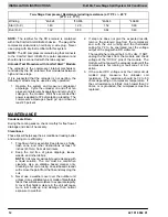
NOTE: 67% compressor capacity translates to
approximately 80% cooling or heating capacity at the
indoor coil.
The compressor will always start unloaded and stay
unloaded for five seconds even when the second stage
of the thermostat is calling for more capacity (a starting
advantage under low voltage conditions).
TROUBLESHOOTING
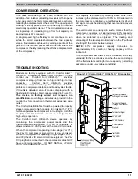
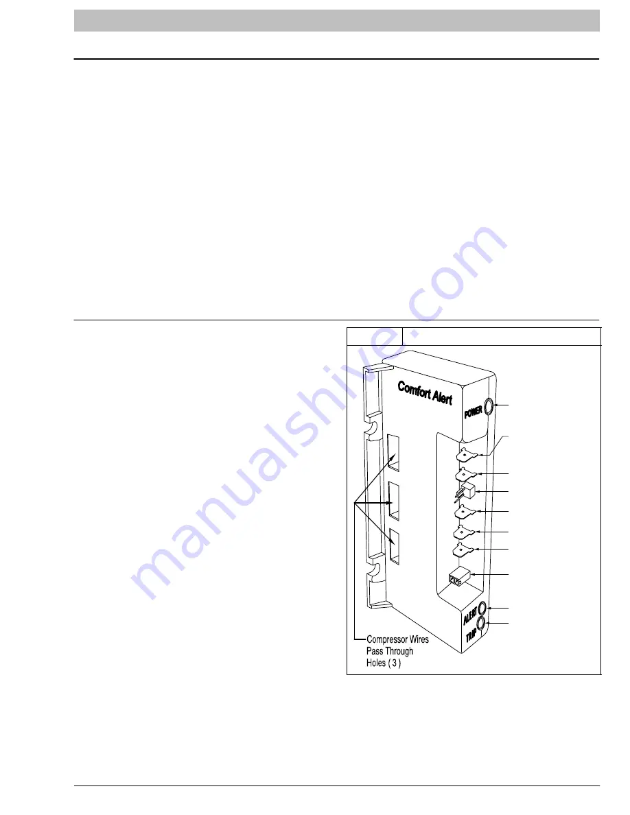
Models are factory equipped with the Comfort Alert
UltraTech
Diagnostics device (refer to Figure 12) in the
control box. Comfort Alert UltraTech
provides
compressor staging from low to high and high to low
capacity. Comfort Alert UltraTech provides
around−the−clock monitoring for common electrical
problems, compressor defects, and broad system faults.
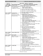
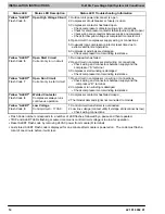
If trouble is detected, an alert code is displayed with a
flashing LED indicator. Alert codes are listed in Figure 13.
The device is factory wired and requires no
modification. Low voltage lead wires are provided in the
control box for connection to thermostat wires (use wire
nuts).
The Comfort Alert UltraTech must be powered to properly
stage compressor to high capacity. Energizing the Y (Y1)
terminal operates the compressor in low−stage. Both the
Y (Y1) and Y2 terminals must be energized for
high−stage operation.
The Comfort Alert UltraTech device operates by
monitoring the compressor power leads and the
thermostat demand signals Y (Y1) and Y2 terminals. It
draws constant 24 VAC power at the R and C terminals.
When the compressor is operating in low−stage (Y or Y1),
the 24v DC compressor solenoid coil is de−energized.
When the compressor is operating in high−stage (Y or Y1
and Y2), the 24v DC solenoid coil is energized. The 24v
DC plug that is connected to the compressor does NOT
have an internal rectifier. DO NOT INSTALL A PLUG
WITH INTERNAL RECTIFIER.
Figure 12 Comfort Alert
t
UltraTech
t
Diagnostics
Y2
Y
L
R
C
R
C
S
“Power” LED
Thermostat Demand
1
st
Stage Compressor
Data Port
Thermostat Signal
24 VAC HOT
24 VAC Common
DC Compressor
Solenoid
“Alert” LED
“Trip” LED
Thermostat Demand
2
nd
Stage Compressor


